Pontoon Ignition Switch Wiring Diagram – The first step is to look at the various types of terminals that are used on the ignition switch. They include terminals for the Ignition switch, Coil, and Accessory. After we’ve identified the purpose of these terminals, we can determine the various components of the ignition wiring. We will also talk about the functions as well as the Coil. After that we will discuss the Accessory Terminals.
The terminals of the ignition switch
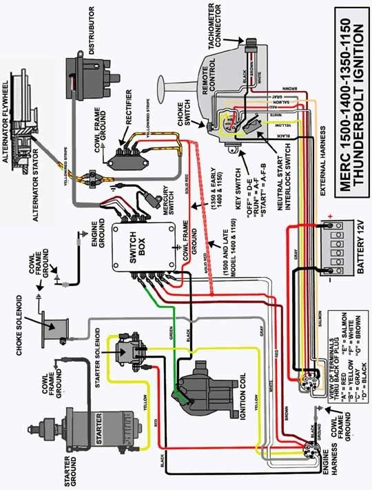
The ignition switch is comprised of three different switches that direct the battery’s current to different destinations. The first switch is used to power the choke by pushing it, and another switch controls the ON/OFF position. Each manufacturer has its individual color-coding system that we’ll discuss in a subsequent article. OMC uses this method. The ignition switch comes with a connector for adding the tachometer.
Although the majority of ignition switch terminals are duplicated, the numbers might not match the diagram. To make sure that your wires are plugged in to the ignition switch, it is recommended to check their continuity. This can be done with a cheap multimeter. Once you are satisfied that all wires are running in good harmony, you can attach the new connector. The wiring loom for an ignition switch that is supplied by the manufacturer will differ from the one that you have in your vehicle.
It is essential to know the ways in which the ACC outputs and auxiliary outputs function to connect them. The ACC, IGN and START terminals are the default connections to the ignition switch. They also serve as the main connections to the radio and stereo. The ignition switch is accountable to turn the engine of your car on and off. Older cars are equipped with ignition switch terminals marked “ACC” or “ST” (for individual magnetowires).
Terminals for coil
The terminology used to determine the type and model of the ignition coil is the primary thing. You’ll see a number of connections and terminals within the basic wiring diagram for ignition which includes two primary and two secondary. Each coil has an operating voltage. The first step to determine the type you have is to check the voltage at S1 or the primary terminal. Also, you should examine S1 for resistance to determine whether it is an A, B, or C coil.
The coil’s low-tension side should be connected to the chassis’s minus. This is the ground of the ignition wiring. The high-tension side is a positive connection to the sparkplugs. It is required for the purpose of suppression that the coil’s metallic body be connected to its chassis, however, it is not necessary. The diagram of the ignition wiring will also outline the connections of the positive coil terminals. In some cases scanning your local auto parts store will be able to diagnose defective ignition coils.
The black-and-white-striped wire from the harness goes to the negative terminal. The other white wire is black and goes to the terminal opposite. The black wire goes to the contact breaker. You can examine the connections with a pencil to pull the wires out from the housing. You should also check to ensure that the terminals aren’t bent.
Accessory Terminals
![]()
The ignition wiring diagrams illustrate the different wires that power the various components of the vehicle. Each part has four distinct connections that are color coded. Accessories are red while the battery is yellow and the starter solenoid green. The “IGN” terminal is used for starting the car, operating the wipers and various other functions. This diagram shows how to connect ACC and ST terminals with the rest of components.
The terminal BAT holds the battery. Without the battery the electrical system will not start. A dead battery could make the switch not come on. It is possible to view the wiring diagram of your car to see the location of your car’s batteries. placed. The accessory terminals of your car are connected with the battery and the ignition button. The BAT connector connects to your battery.
Some ignition switches come with an additional “accessory position” which allows users to adjust their outputs independently of the ignition. Sometimes, a customer wants to make use of an auxiliary output that is separate from the ignition. In order to use the auxiliary output, connect the connector with the same colors as the ignition, connecting it to the ACC terminal on the switch. Although this is a fantastic feature, there’s something you need to know. Some ignition switches are configured to be in an ACC position when the vehicle is in the ACC position. They’ll also be in the START mode after the vehicle has been moved into the IGN position.
Gallery of Pontoon Ignition Switch Wiring Diagram

Gallery of Pontoon Ignition Switch Wiring Diagram


