Pro Comp Ignition Wiring Diagram – The first step is to look at the different terminals used on the ignition switch. These include terminals for Coil, Ignition Switch, and Accessory. After we’ve identified the purpose of these terminals and what they do, we can then determine the various components in the ignition wiring. We will also discuss the functions for the Ignition switch as well as the Coil. Then, we’ll turn our attention to the Accessory terminals.
Terminals for the ignition switch
An ignition switch is composed of three switches. They are responsible for supplying the battery’s power to various locations. The first one is utilized to turn on the choke by pushing it, while the third switch is used to control the ON/OFF setting. Different manufacturers utilize their own color-coding method for the various conductors, that is described in a separate article. OMC follows the same system. The ignition switch is also equipped with an option to connect the tachometer.
Although some ignition switch terminals may not be authentic, the numbering of each one might not be in line with the diagram. Before plugging into the ignition switch ensure that you check the continuity. This can be done with a multimeter that is inexpensive. After you’re happy with the continuity of the wires, then you’ll be able install the new connector. The wiring loom used in a factory-supplied ignition system switch differs.
For connecting the ACC outputs to the auxiliary outputs on your car, you need first know the way these two connections function. The ACC terminals as well as the IGN terminals are the standard connections for your ignition switch. The START and IGN connections are the primary connections for stereo and radio. The ignition switch turns the engine of your car ON and off. On older vehicles the terminals of the ignition switch are marked with the alphabets “ACC” and “ST” (for individual magnet wires).
Terminals for coil
To identify the kind of ignition coil, the first step is to learn the terms. An ignition wiring diagram will reveal a variety of terminals and connections comprising two primary and two secondaries. Each coil has a specific operating voltage. To determine the type of coil you have the first step is to test the voltage at S1, the primary terminal. S1 should be examined for resistance to determine if the coil belongs to Type A, B, and/or C.
The negative of the chassis must be connected to the low-tension side. This is the wiring diagram you will find in the diagram of wiring. The high-tension part provides the spark plugs with positive. To reduce the noise, the coil’s body metal must be connected to the chassis. This is not necessary for electrical use. There are also connections of the positive and negative coil terminals on the diagram of the ignition wiring. It is possible to find an issue with the ignition coil which can be identified by scanning it at an auto parts store.
The black-and-white-striped wire from the harness goes to the negative terminal. The positive terminal receives the white wire, which has a trace in black. The black wire is connected to the contactbreaker. To test the wires’ connections, use a paperclip to lift them from the housing. Also, make sure to ensure that the terminals haven’t been bent.
Accessory terminals
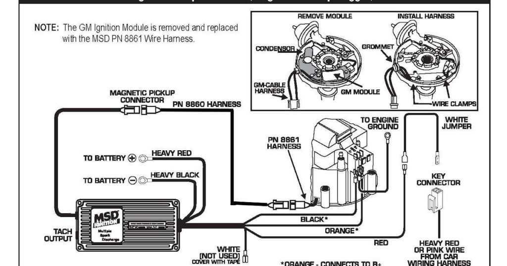
The ignition wiring diagrams show the various wires utilized to power the different components. Typically, there are four different colored terminals for each part. The red color is for accessories, yellow to the battery, and green for the starter solenoid. The “IGN terminal is used for starting the car, operating the wipers, and for other functions. The diagram below shows how to connect the ACC terminal as well as the ST terminals to other components.
The terminal BAT is the connector for the battery. The electrical system can’t be started without the battery. The switch won’t be able to turn off if the battery isn’t present. It is possible to look up your wiring diagram to figure out the location of your car’s batteries. placed. The accessory terminals of your car connect to the ignition switch as well as the battery. The BAT terminal is connected to the battery.
Some ignition switches come with an additional “accessory position” that allows users to alter their outputs without the ignition. Sometimes, users want to utilize an additional output that is independent of the ignition. For the auxiliary output to be used, wire the connector with the same shade as that of the ignition. Then connect it with the ACC end of the switch. Although this is a fantastic feature, there’s one thing you need to know. Most ignition switches are set to have an ACC position when the vehicle is in the ACC position, while they’re in the START position when the vehicle is in the IGN position.
Gallery of Pro Comp Ignition Wiring Diagram
Gallery of Pro Comp Ignition Wiring Diagram


