Push Button Ignition Switch Wiring Diagram – Let’s first examine the various terminals used on the ignition switch. They include terminals that are used for Coil, Ignition Switch, and Accessory. After we’ve established what these kinds of terminals are used for We will then identify the different parts of the Push Button Ignition Switch Wiring Diagram. We’ll also go over the functions of the Ignition switch and Coil. After that, we’ll turn our attention to the Accessory terminals.
Ignition switch terminals
There are three switches on the ignition switch, and they feed the battery’s voltage to several different places. The first switch provides power to the choke whenever it is pushed. The second is the switch that controls the ignition’s ON/OFF positions. Different manufacturers use various color codes for the different conductors. This is discussed in a different article. OMC uses this system. The ignition switch is also equipped with an option to connect the timer.
While the majority of ignition switch terminals don’t carry an initial number, they could have a different number. To make sure that the wires are correctly connected to the switch, you must verify their continuity. You can check this using a simple multimeter. After you’re happy with the continuity of the wires, then you’ll be able to install the new connector. If you are using an ignition switch that is supplied by the manufacturer, the wiring loom is distinct from the one that is used in your vehicle.
Before connecting the ACC outputs to the auxiliary outputs of your car It is essential to understand the basics of these connections. The ACC, IGN and START terminals are your default connection to the ignition switch. They are also the primary connections to the radio and stereo. The ignition switch switches the engine of your car ON and off. On older vehicles the terminals of the ignition switch are marked with the initials “ACC”, and “ST” (for the individual magnet wires).
Coil terminals
The first step in determining the kind of ignition coil is to know the terms used. There are a variety of connections and terminals within an ignition wiring schematic that include two primary and two secondary. Each coil operates at a specific voltage. The first step in determining which kind of coil you’re dealing with is to test the voltage on S1, or the primary terminal. To determine if it is a Type A, C, or B coil, you must also check the resistance of S1.
The lower-tension side of the coil must be connected to the chassis’ negative. This is what’s called the ground in the diagram of the ignition wiring. The high tension side supplies positively directly to the spark plugs. To reduce the noise the coil’s metal body is required to be connected to the chassis. It’s not necessary for electrical use. A wiring diagram can also depict the connection between positive and negative coils. You may find an issue with the ignition coil which can be identified by scanning it at an auto parts retailer.
The black-and-white-striped wire from the harness goes to the negative terminal. The negative terminal is served by the black trace joined to the white wire. The black wire is connected to the contactbreaker. It is possible to remove the black wire from the housing of the plug with a paper clip in case you are uncertain about the connection. It’s also crucial to ensure that the terminals do not bend.
Accessory terminals
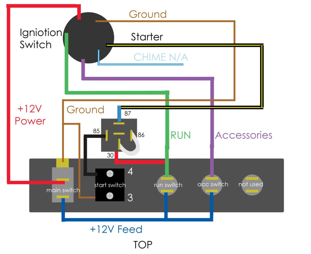
Diagrams of ignition wiring show the various wires that are used to power the different components. In general, there are four different colors-coded terminals that are used for each component. To identify accessories, red is for starter solenoid, yellow for battery and blue for accessory. The “IGN terminal is used for starting the car, operating the wipers, and for other functions. The following diagram shows how to connect both the ACC terminal as well as the ST terminals to various components.
The terminal BAT holds the battery. Without the battery the electrical system will not start. A dead battery can cause the switch to stop turning on. You can refer to your wiring diagram if not sure where the batteries of your car are located. The ignition switch is linked to the car’s battery. The BAT Terminal is connected to the battery.
Certain ignition switches have an additional position. It allows users to access their outputs from another location without having to turn on the ignition. Customers sometimes want the auxiliary output to be used independently from the ignition. The auxiliary output is utilized by wiring the connector in the same colors as your ignition and attaching it to the ACC terminal of the switch. While this is an excellent feature, there’s one thing you should know. The majority of ignition switches have an ACC position when the vehicle is in the ACC however they will be at the START position if the car is in IGN.
Gallery of Push Button Ignition Switch Wiring Diagram
Gallery of Push Button Ignition Switch Wiring Diagram


