Push Button Ignition Wiring Diagrams – We’ll begin by looking at the various types of terminals in an ignition switch. These are the terminals used for Coil, Ignition Switch, and Accessory. Once we know which terminals are used then we can recognize the various parts of the Push Button Ignition Wiring Diagrams. We will also cover the roles of both the Ignition Switch and Coil. We’ll then turn our attention to the accessory terminals.
The terminals of the ignition switch
An ignition switch is comprised of three switches. They feed the battery’s voltage to different locations. The first is used to power the choke by pushing it, while the second is for the ON/OFF setting. Different manufacturers have different color-coding systems that correspond to the conductors. OMC uses this system. An adapter is included on the ignition switch to allow the installation of an Tachometer.
Although the majority of ignition switch terminals do not have an initial number, they could have a different number. Before plugging into the ignition switch be sure to test the continuity. A simple multimeter will assist you in this. Once you are happy with the continuity of the wires, connect the new connector. The wiring loom of the ignition switch supplied by the factory will be different from the one in your car.
Before you can connect the ACC outputs to your car’s auxiliary outputs It is essential to know the fundamentals of these connections. The ACC and IGN terminals are the default connections on the ignition switch. the START and IGN terminals are the primary connections for the stereo and radio. The ignition switch is the one that turns the engine of your car to and off. The terminals on older cars ignition switches are identified with “ACC” and ST (for specific magneto wires).
Terminals for coil
Understanding the terms utilized is the first step in determining the kind of ignition coil you need. In a simple diagram of the wiring for ignition you’ll see a number of different terminals and connections, including two primary and two secondary. The coils are equipped with a particular operating voltage, and the first step in determining which type you’re using is to test the voltage at S1, the primary terminal. S1 must also be inspected for resistance to determine whether it’s an A, Type B, or an A coil.
The chassis’ negative end should be connected to the coil’s low-tension side. This is the ground in the wiring diagram for ignition. The high-tension supply delivers the spark plugs with positive electricity directly. It is required for the purpose of suppression that the body of the coil’s metal be connected to the chassis, but not essential. It is also possible to see the connections between the positive and negative coil’s terminals on an diagram of the ignition wiring. Sometimes, a visit to an auto parts shop can detect a defective ignition wire.
The black-and-white-striped wire from the harness goes to the negative terminal. The positive terminal also receives a second white wire, which has a black trace. The black wire connects with the contact breaker. If you’re not certain about the connections between the twowires, use the clip of a paperclip to remove them from the housing of the plug. Be sure to verify that the connections aren’t bent.
Accessory terminals
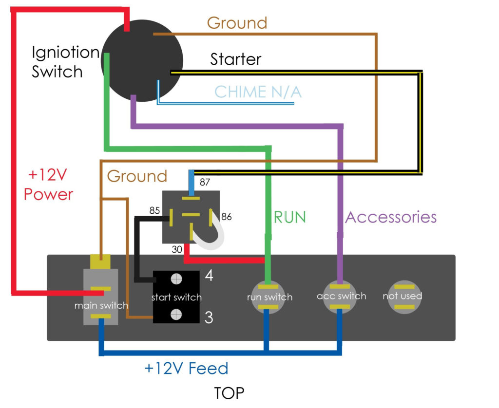
Diagrams of ignition wiring show the various wires utilized to power different components. There are usually four colors-coded terminus of each part. Red refers to accessories, yellow the battery and green is the starter solenoid. The “IGN” terminal can be used to turn on the car, operate the wipers, and other functions. The diagram shows the connections to the ACCand ST terminals.
The terminal referred to as BAT is the location where the battery is. The electrical system will not start in the event that the battery isn’t connected. A dead battery could cause the switch to stop turning on. If you’re not sure the exact location where the battery in your car is located, you can review the wiring diagram of your car to determine how to locate it. The accessory terminals in your car are connected to the battery as well as the ignition button. The BAT connector connects to your battery.
Some ignition switches feature an additional “accessory” position, where users can control their outputs with no ignition. Customers may want to utilize the auxiliary output in addition to the ignition. Use the additional output by connecting the connector to an ACC terminal on your switch with the same colors. While this is an excellent option, there’s an significant difference. Most ignition switches are configured to be in an ACC position when the car is in the ACC position, while they’re in the START position when the vehicle is in the IGN position.
Gallery of Push Button Ignition Wiring Diagrams
Gallery of Push Button Ignition Wiring Diagrams


