Push To Choke Boat Ignition Switch Wiring Diagram – Let’s begin by looking at the various kinds of terminals that are found in an ignition switch. These are the terminals that connect the Ignition, Coil, or Accessory. After we’ve identified the purpose of the terminals we will be able to recognize the various parts of the ignition wiring. In addition, we will discuss the functions of both the Ignition Switch and the Coil. Next, we’ll discuss the function of the Ignition switch as well as Coil.
Terminals for the ignition switch
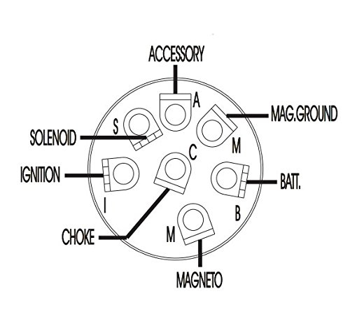
There are three different switches in the ignition switch, and they provide the battery’s voltage to several different destinations. The ON/OFF position of the switch that controls the ignition is managed by the first switch, which supplies power to the choke whenever it’s pulled. Different manufacturers use different color-coding methods to identify different conductors. We’ll discuss this in a separate article. OMC uses this method. An additional connector is included in the ignition switch for connecting the to a tachometer.
While most ignition switch terminals are duplicated, the numbers might not match the diagram. Before you plug in the ignition switch, be sure to test the continuity. This can be done with a simple multimeter. Once you’re satisfied about the continuity of your wires, you will be able to connect the new connector. If your car has an original ignition switch supplied by the factory (or wiring loom) the wiring loom might differ from that of the car.
The first step is to understand the distinctions between ACC and auxiliary outputs. The ACC and IGN connectors are the standard connections of the ignition switch. The START, IGN, and ACC terminals are the main connections to the radio or stereo, the START/IGN terminals are the primary ones. The ignition switch turns the car’s engine on and off. The terminals of older cars ignition switches are marked by “ACC” as well as ST (for specific magneto wires).
Coil terminals
Understanding the terminology is the initial step in knowing what type of ignition coil you have. There are a variety of connections and terminals within an ignition wiring schematic which includes two primary and two secondary. Each coil is operating at a certain voltage. The first step to determine which type you’re dealing with is to test the voltage at S1 or the primary terminal. S1 should also be tested for resistance to determine whether it’s an A, Type B, or an A coil.
The coil’s low-tension end must be connected with the chassis’ positive. This is also the ground in the ignition wiring diagram. The high-tension supply delivers positive directly to spark plugs. To prevent noise the coil’s metal body is required to be connected to the chassis. It is not required for electrical use. The wiring diagram will also depict the connection between positive and negative coils. There could be an issue with the ignition coil that can be easily diagnosed by scanning it at the auto parts shop.
The black-and-white-striped wire from the harness goes to the negative terminal. The terminal that is negative is served by the trace in black that’s attached to the white wire. The black wire connects to the contact breaker. If you’re not sure about the connections of the twowires, use the clip of a paperclip to remove them from the housing of the plug. Be sure that the terminals aren’t bent.
Accessory terminals
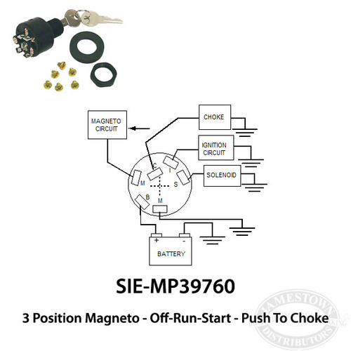
The ignition wiring diagrams illustrate the different wires that are used to power various components of the car. In general there are four distinct colors-coded terminals that are used for each component. To identify accessories, red stands for starter solenoid, yellow is for battery, and blue for accessory. The “IGN terminal allows you to start the car, manage the wipers or other operation features. The diagram below illustrates how to connect the ACC terminal and ST terminals to various components.
The terminal BAT connects the battery to the charger. The electrical system won’t start without the battery. The switch also won’t be able to turn on without the battery. The wiring diagram will show you the location of the battery of your car. The ignition switch and the battery are connected through the accessory terminals. The BAT connector is connected to the battery.
Some ignition switches have an “accessory” setting that allows users to control their outputs without needing to utilize the ignition. Some customers want the auxiliary output to be operated independently of the ignition. The auxiliary output is connected to connect the connector in the same color as your ignition and connecting it to the ACC terminal of the switch. This is a great option, but there’s an important difference. Many ignition switches have an ACC position when the car is in ACC mode and a START position when you are in IGN.
Gallery of Push To Choke Boat Ignition Switch Wiring Diagram

Gallery of Push To Choke Boat Ignition Switch Wiring Diagram


