Quick Car Ignition Control Panel Wiring Diagram – First, let’s take a look at the different types of terminals used on the ignition switch. These include the terminals for the Ignition switch, Coil, and Accessory. Once we’ve determined the function of these terminals, it is possible to determine the various components of the ignition wiring. In addition, we will discuss the function of the Ignition switch and Coil. We’ll then turn our attention on the accessory terminals.
Terminals for ignition switch
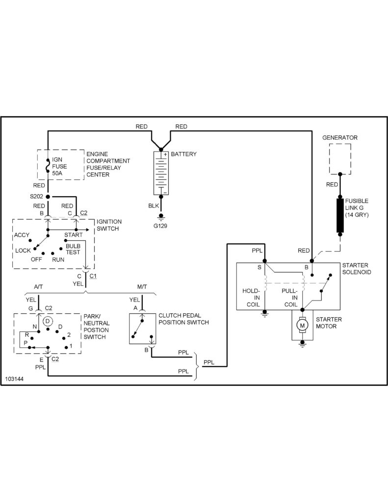
An ignition switch has three separate switches that feed the battery’s current to different destinations. The first one supplies the choke with power when it is pushed. The second is the ignition switch’s ON/OFF position. Different manufacturers have distinct colour-coding systems that correspond to the conductors. OMC utilizes this system. Connectors can be connected to the ignition switch to include an electronic tachometer.
Although the majority of ignition switch terminals may not be original, the numbering for each may not match the diagram. Check the continuity of all the wires to ensure that they are properly plugged into the ignition switches. This can be accomplished using a cheap multimeter. After you’re satisfied with the integrity of the wires install the new connector. If you have a factory-supplied ignition switch the wiring loom will be distinct from the one that is in your car.
It is essential to know the way that ACC outputs and the auxiliary outputs function to connect them. The ACC/IGN terminals function as the default connections on the ignition switch. The START/IGN terminals connect to the stereo or radio. The ignition switch operates the engine’s on/off button. Older vehicles are identified with the initials “ACC”, “ST”, (for individual magneto cables) on their ignition switch terminals.
Terminals for coil
The first step in determining the type of ignition coil is to understand the terminology used. The diagram of the basic ignition wiring illustrates a variety of connections and terminals. There are two primary and one secondary. The coils come with a distinct operating voltage, and the first step to determine which one you’ve got is to check the voltage at S1, the primary terminal. S1 should also be checked for resistance to determine whether it’s an A, Type B, or A coil.
The negative end of the chassis end should be connected to connect the coil’s low-tension side. This is also the ground on the wiring diagram for ignition. The high tension side provides positively directly to the spark plugs. To reduce the noise the body of the coil must be connected to chassis. But, it’s not required to connect electrically. You will also see the connections of the negative and positive coil’s terminals on the diagram of the ignition wiring. In some cases, you’ll find that the ignition coil is damaged and is easily identified with scanning at an auto parts store.
The black-and-white-striped wire from the harness goes to the negative terminal. The positive terminal also receives the second white wire, which includes a black trace. The black wire is connected to the contact breaker. If you’re not certain about the connections of the two, try using a paper clip to remove them from the plug housing. You should also check to make sure that the connections are not bent.
Accessory terminals
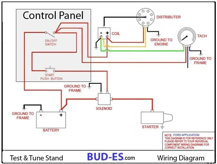
Ignition wiring diagrams show the different wires that are utilized to power the vehicle’s various parts. There are typically four terminals with color codes that are connected to the component. Accessories are red while the battery is yellow, the starter solenoid is green. The “IGN” terminal is used to start the vehicle and control the wipers, as well as other operating features. The diagram demonstrates how to connect the ACC and ST terminals to the other components.
The terminal BAT holds the battery. The battery is vital for the electrical system to get started. Additionally, the switch won’t begin to turn on. It is possible to look up your wiring diagram to figure out where your car’s batteries are placed. The ignition switch is connected to the battery of your car. The BAT terminal connects to the battery.
Some ignition switches offer the option of an “accessory position” that allows users to adjust their outputs independently of the ignition. Some customers prefer to make use of an additional output independent of the ignition. The auxiliary output could be connected by wiring the connector with the same color as your ignition and attaching it to the ACC terminal of the switch. Although this is a great option, there’s a thing you should know. The majority of ignition switches have an ACC position when the vehicle is in ACC however they will be in the START position if the vehicle is IGN.
Gallery of Quick Car Ignition Control Panel Wiring Diagram
Gallery of Quick Car Ignition Control Panel Wiring Diagram


