Quickcar Ignition Panel Wiring Diagram – Let’s first examine the different types and purposes of the terminals found on the ignition switches. They include terminals for Coil, Ignition Switch, and Accessory. Once we’ve determined the function of the terminals it is possible to recognize the various parts of the ignition wiring. We’ll also go over the functions for the Ignition switch and the Coil. Following that, we’ll shift our attention to Accessory terminals.
The ignition switch’s terminals
An ignition switch is comprised of three switches. They feed the battery’s voltage to many different locations. The ON/OFF setting of the switch that controls the ignition is managed by the second switch, which provides power to the choke when it’s pulled. Different manufacturers have different color-coding systems to identify different conductors. This will be covered in another article. OMC employs this system. Connectors can be connected to the ignition switch in order to include an electronic Tachometer.
Although most ignition switch terminals are duplicated, the number may not match the diagram. Verify the continuity of the wires first to ensure they’re properly connected to the ignition switch. This can be accomplished using a simple multimeter. Once you’re satisfied about the continuity of the wires, then you’ll be able to install the new connector. If you have an ignition switch that is supplied by the manufacturer the wiring loom will be different from the one used in your vehicle.
To connect the ACC outputs to the auxiliary outputs on your vehicle, you have to understand how these two connections work. The ACC and IGN connectors are the default connections of the ignition switch. Although the START, IGN, and ACC terminals are primary connections to the radio or stereo, the START/IGN terminals are the main ones. The ignition switch turns the car’s engine on and off. Older cars have the ignition switch terminals marked “ACC” or “ST” (for individual magnetowires).
Terminals for coil
The first step to determine the kind of ignition coil is to know the terminology used. In a basic ignition wiring diagram, you will see various connections and terminals, which include two primary and two secondary. The coils have a specific operating voltage, and the first method of determining what type you’re using is to test the voltage at S1, the main terminal. S1 must also be subjected to resistance testing to determine if it are a Type A or B coil.
The lower-tension side of the coil must be connected to the chassis the negative. This is also the ground on the diagram of the ignition wiring. The high-tension part provides the spark plugs with positive. It is required for suppression purposes that the metallic body of the coil is connected to its chassis however it isn’t essential. The wiring diagram for ignition will also outline the connection of the positive coil’s terminals. Sometimes, a check at an auto part store can identify a problem with the ignition wire.
The black-and-white-striped wire from the harness goes to the negative terminal. The positive terminal also receives the second white wire, which includes a black trace. The contact breaker is connected to the black wire. To check the connection, use a paperclip or a pencil to remove them from the plug housing. Make sure that the terminals don’t bend.
Accessory terminals
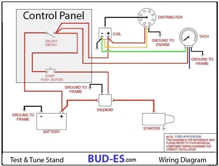
The diagrams for ignition wiring illustrate the wiring used to power the vehicle’s electrical supply. There are typically four colored terminals for each component. The red color is used for accessories while yellow is the battery, while green is the starter solenoid. The “IGN” terminal is used to turn on the car and operate the wipers, as well as other operating functions. This diagram demonstrates how to connect ACC and ST terminals with the rest of the components.
The terminal BAT is the connector for the battery. The electrical system will not start without the battery. The switch also won’t be able to turn on without the battery. You may refer to the wiring diagram if you’re uncertain about where the car’s batteries are. The accessory terminals in your car are connected to the battery as well as the ignition button. The BAT terminal is connected to the battery.
Certain ignition switches have a separate “accessory” position, in which users can manage their outputs without the ignition. Some customers might want to use the auxiliary output separately from the ignition. You can use the additional input by connecting it to the ACC terminal. This is an excellent option, but there’s an important difference. The majority of ignition switches have an ACC position when the vehicle is in ACC however, they will be in the START position when the vehicle is in IGN.
Gallery of Quickcar Ignition Panel Wiring Diagram
Gallery of Quickcar Ignition Panel Wiring Diagram


