Quicksilver Ignition Switch Wiring Diagram – We will first look at the various types and purposes of the terminals that are found in the ignition switches. These terminals comprise the Ignition switch and Coil as well as the Accessory. Once we know the purpose of these terminals are used for then we can discover the various components of the Quicksilver Ignition Switch Wiring Diagram. We’ll also go over the roles of the Ignition switch and Coil. Then, we will turn our attention towards the accessories terminals.
Ignition switch terminals
An ignition switch is comprised of three switches. They feed the battery’s voltage to different locations. The first switch powers the choke. The third switch regulates the ON/OFF switch of the ignition switch. Different manufacturers use different color-coding methods for different conductors. We will cover this in a different article. OMC utilizes this method. The ignition switch is also equipped with an option to connect the tachometer.
Although the majority of ignition switch terminals are duplicated, the number may not match the diagram. To ensure that the wires are properly connected to the ignition switch you should check their continuity. A multimeter is an excellent instrument to verify the continuity. After you’re satisfied with the connection then you can connect the new connector. The wiring loom used for an ignition switch that’s factory-supplied will be different than the one that you have in your vehicle.
You must first understand how the ACC outputs and the auxiliary outputs function in order to join them. The ACC and IGN connectors are the default connections for the ignition switch. The START, IGN, and ACC terminals are the main connections to the radio or stereo, the START/IGN terminals are the main ones. The ignition switch’s function is for turning the car’s engine on and off. The ignition switch terminals on older cars are labeled with the initials “ACC” as well as “ST” (for each magneto wires).
Terminals for coil
Understanding the terms is the initial step towards knowing what type of ignition coil you have. A basic ignition wiring diagram will display a range of connections and terminals, which include two primary terminals and two secondaries. You need to determine the type of coil that you own by examining the voltage on the primary terminal S1. It is also recommended to test S1 for resistance to identify if it’s a Type A B, C, or coil.
The chassis’ negative needs to be connected to the side of low-tension. It is also the ground in an ignition wiring diagram. The high-tension component supplies the positive power directly to the spark plugs. The body of the coil has to connect to the chassis for suppression purposes but is not electrically essential. The wiring diagram will depict the connection between positive and negative coils. Sometimes, a damaged ignition coil can be detected with a scan at an auto parts shop.
The black-and-white-striped wire from the harness goes to the negative terminal. The white wire is black-colored and connects to the negative terminal. The contact breaker is attached to the black wire. It is possible to check the connections with a pencil to take the wires out from the housing. Make sure that the terminals aren’t bent.
Accessory terminals
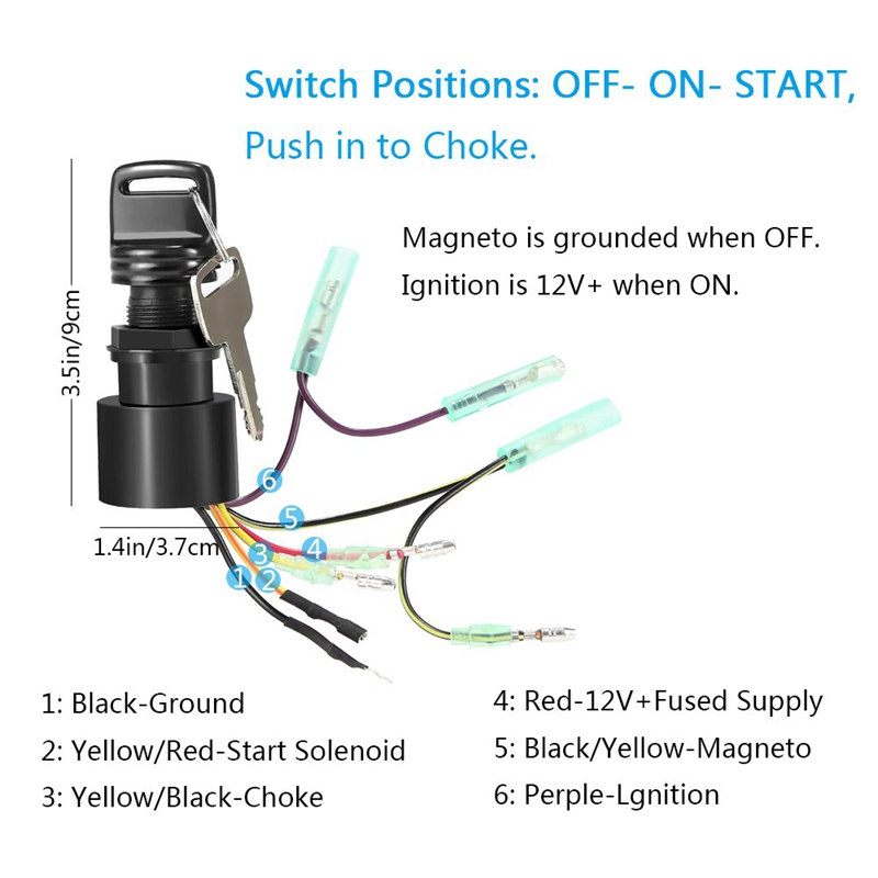
The ignition wiring diagrams illustrate the various wires utilized to power the vehicle’s various parts. There are typically four terminals with color codes that are connected to each component. The red color is used for accessories and yellow is for the battery, and green is for the starter solenoid. The “IGN” terminal can be utilized to turn on the car, control the wipers, as well as other features. The below diagram illustrates how to connect the ACC terminal and ST terminals to other components.
The battery is connected to the terminal called BAT. Without the battery the electrical system will not get started. The switch won’t be able to turn off if the battery isn’t present. A wiring diagram can show you the location of the battery in your car. The accessory terminals of your vehicle connect to the battery as well as the ignition switch. The BAT Terminal is connected to the battery.
Certain ignition switches have an additional position. It allows users to access their outputs from another location without the ignition. Some customers may prefer to use the auxiliary output separately from the ignition. Make use of the secondary output by connecting it to an ACC terminal on your switch that has the same color. This feature of convenience is fantastic however, there’s one distinction. The majority of ignition switches have an ACC position if the car is in the ACC however they will be in the START position when the vehicle is IGN.
Gallery of Quicksilver Ignition Switch Wiring Diagram
Gallery of Quicksilver Ignition Switch Wiring Diagram


