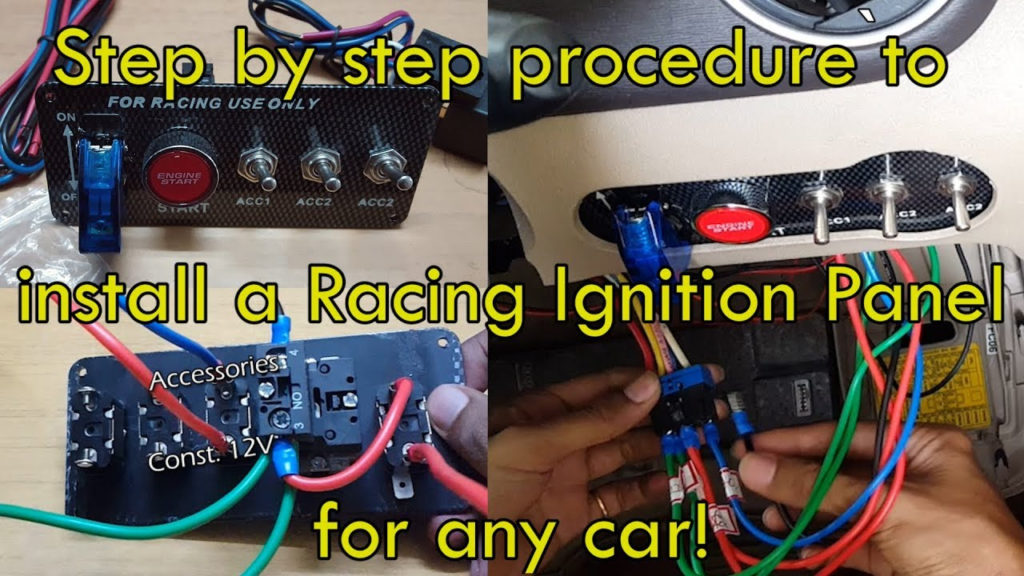
Race Car Ignition Switch Wiring Diagram – First, we will examine the various types of terminals found in the ignition switch. These are terminals for Coil, Ignition Switch, and Accessory. After we’ve identified the terminals used and which ones are not, we can determine the various components of the Race Car Ignition Switch Wiring Diagram. In addition, we will discuss the roles of the Ignition switch and Coil. After that, we will turn our attention towards the accessories terminals.
The terminals are for ignition switches.
The ignition switch is comprised of three separate switches that feed the battery’s current to different locations. The first one supplies power to the choke when it is pushed. The third is the position of the ignition switch’s ON/OFF. Each manufacturer has their unique color-coding system, which we’ll discuss in a subsequent article. OMC follows this scheme. There is a connector in the ignition switch to allow attaching an to a tachometer.
While some ignition switch terminals do not appear in their original configuration The numbering might not match that of the diagram. It is important to first verify the electrical continuity to ensure that they are plugged into the ignition switch correctly. This can be accomplished with a simple multimeter. When you’re satisfied that all wires are running in good harmony, you can attach the new connector. The wiring loom for an ignition switch that is supplied by the factory will be different from the one that you have in your car.
Knowing how the ACC outputs are connected to the auxiliary outputs inside your car is essential. The ACC terminals as well as the IGN terminals function as the primary connections to the ignition switch. The START and IGN connections are the most important connections for radio and stereo. The ignition switch’s function is to turn the engine of your car on and off. Older cars are identified by the alphabets “ACC”, “ST”, (for individual magneto cables) on their ignition switch terminals.
Coil terminals
The first step in determining the kind of ignition coil is to understand the terminology used. In a typical diagram of the wiring for ignition there are several different connections and terminals, which include two primary and two secondary. Each coil is operating at a certain voltage. The first step in determining which kind you have is to check the voltage of S1 or the primary terminal. S1 must be tested for resistance in order to identify if the coil is Type A, B, or C.
The coil’s low-tension side should be connected at the chassis’s minus. This is the ground on the wiring diagram for ignition. The high-tension part connects the spark plugs to a positive. It is necessary to suppress the body of the coil’s metal be connected to its chassis but not essential. The diagram of the ignition wiring will also show the connections of the positive coil terminals. In certain cases scanning your local auto parts shop will help identify the malfunctioning ignition coils.
The black-and-white-striped wire from the harness goes to the negative terminal. The positive terminal receives the other white wire with the trace in black. The black wire is connected to the contact breaker. If you’re not sure about the connection between both, you can use a paper clip to remove them from the plug housing. Also, make sure that the connections aren’t bent.
Accessory terminals
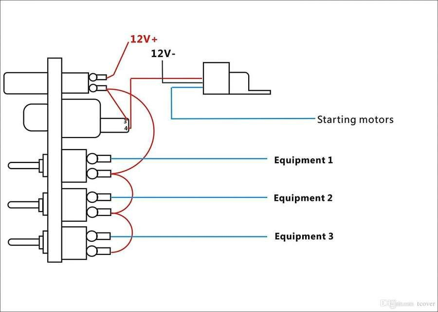
Diagrams of ignition wiring depict the wiring used to provide power to various components of the car. There are typically four different color-coded terminus for each component. Accessories are red, the battery is yellow the starter solenoid green. The “IGN terminal allows you to start the car, control the wipers, or any other functions. The diagram illustrates how to connect ACC or ST terminals and the rest.
The terminal called BAT is the place where the battery is. The electrical system cannot start without the battery. A dead battery could make the switch not turn on. It is possible to look up your wiring diagram to determine where your car’s batteries are located. The ignition switch is connected to the car’s battery. The BAT Terminal is connected to the Battery.
Some ignition switches offer an additional “accessory position” that lets users adjust their outputs independently of the ignition. In some cases, users may want to use the auxiliary input independently of the ignition. You can utilize the auxiliary input by connecting it to the ACC terminal. Although this is a fantastic feature, there’s something you need to know. Most ignition switches will have an ACC position if the car is in ACC however, they will be in the START position if the car is in IGN.
Gallery of Race Car Ignition Switch Wiring Diagram
Gallery of Race Car Ignition Switch Wiring Diagram


