Riding Lawn Mower Ignition Switch Wiring Diagram – We will first examine the various types of terminals that are found on the ignition switch. These are terminals that are used for Coil, Ignition Switch, and Accessory. Once we have identified the terminals used, we can begin to determine the various components of the Riding Lawn Mower Ignition Switch Wiring Diagram. We’ll also be discussing the functions of the Ignition switch, as well as the Coil. Following that, we will proceed to the Accessory Terminals.
The terminals of the ignition switch
The ignition switch is comprised of three switches that supply the battery’s current to various locations. The first switch supplies the choke with power when it is pushed. The third is the position of the ignition switch’s ON/OFF. Different manufacturers use different color-coding methods for different conductors. We’ll discuss this in another article. OMC utilizes this method. Connectors can be connected to the ignition switch in order to connect an electronic Tachometer.
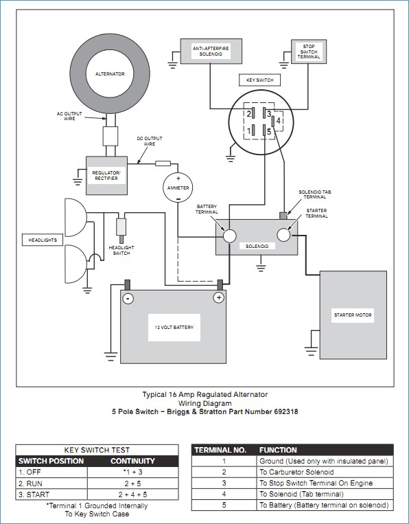
While the majority of the ignition switch terminals aren’t original, the numbers for each may not match the diagram. To ensure that your wires are connected to the ignition switch, it is recommended to check their continuity. A cheap multimeter can help you do this. After you’ve confirmed the continuity of the wires you can connect the connector. The wiring loom for the ignition switch factory-supplied will be different than the one you have in your car.
To connect the ACC outputs to the auxiliary outputs of your car, you’ll need to understand the way these two connections function. The ACC and IGN terminals are the default connections for your ignition switch, and the START and IGN terminals are the principal connections for radio and stereo. The ignition switch is responsible to turn the engine of your car on and off. The terminals on older cars ignition switches are marked with “ACC” and ST (for individual magneto wires).
Terminals for coil
To identify the kind of ignition coil, the initial step is to understand the terminology. You’ll see a number of connections and terminals in the basic wiring diagram for ignition, including two primary, and two secondary. You need to determine the type of coil that you own by examining the voltage at the primary terminal, called S1. S1 should also be checked for resistance in order to identify whether it’s a Type B, B or A coil.
The low-tension side of the coil needs to be connected to the chassis”negative. This is the wiring diagram you will see in the diagram of wiring. The high-tension supply delivers positively directly to spark plugs. It is required for suppression purposes that the metallic body of the coil is connected to its chassis however, it is not necessary. The diagram for the ignition wiring will also show you how to connect the negative and positive coil’s terminals. In certain instances, a scan at the local auto parts store will help identify defective ignition coils.
The black-and-white-striped wire from the harness goes to the negative terminal. The other white wire is black and goes to the terminal opposite. The black wire connects to the contactbreaker. You can take the black wire from the plug housing with a paper clip if you are unsure about the connections. Also, make sure to ensure that the terminals haven’t been bent.
Accessory terminals
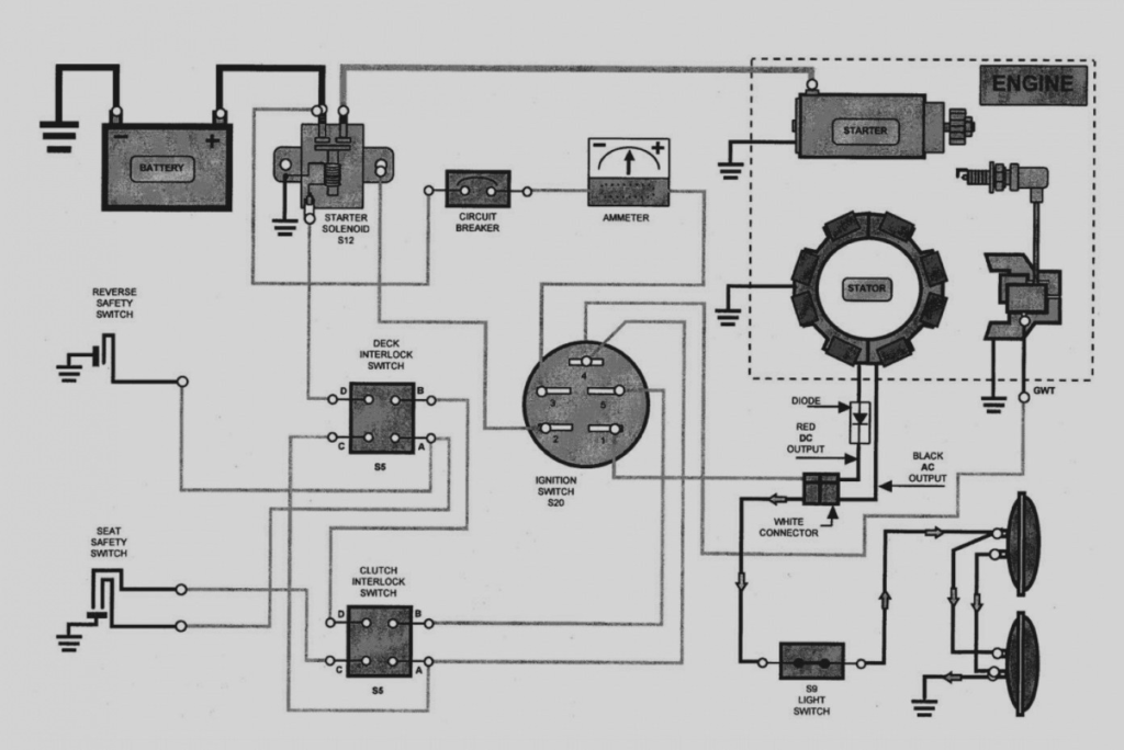
Ignition wiring diagrams depict the various wires that are used for powering the various components. There are usually four different colors of terminals connected to each part. The red symbol represents accessories, yellow is for the battery and green for the solenoid for starters. The “IGN terminal” is used to run the wipers, as well as other operating features. The diagram shows how to connect the ACC and ST terminals to the other components.
The terminal BAT connects the battery to the charger. The electrical system will not start without the battery. Additionally, the switch doesn’t turn on. If you’re not sure of the location of your car’s battery situated, you can review your wiring diagram to see the best way to find it. The ignition switch is connected to the battery of your car. The BAT Terminal is connected to the battery.
Certain ignition switches provide the option of an “accessory position” which allows users to adjust their outputs independently of the ignition. Sometimes, customers want to use the auxiliary output separately from the ignition. The auxiliary output could be connected by wiring the connector with the same colors as your ignition, and then attaching it to the ACC terminal of the switch. While this is an excellent option, there’s a thing you should know. The majority of ignition switches are set to be in an ACC position when the car is in the ACC position, but they’re in the START position when the car is in the IGN position.
Gallery of Riding Lawn Mower Ignition Switch Wiring Diagram
Gallery of Riding Lawn Mower Ignition Switch Wiring Diagram


