S10 Ignition Wiring Diagram – We’ll begin by looking at the different kinds of terminals that are found on an ignition switch. They include terminals for the Ignition switch, Coil, and Accessory. Once we’ve determined the function of the terminals it is possible to recognize the various parts of the ignition wiring. We’ll also go over what functions are available for the Ignition switch, as well as the Coil. We will then discuss the function of the ignition switch and Coil.
Terminals for ignition switches
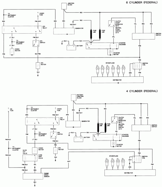
An ignition switch is made up of three different switches. These are responsible for supplying the battery’s power to various locations. The choke is powered by the first switch. The second switch controls the ON/OFF of the ignition switch. Every manufacturer has its own color-coding system, which we’ll go over in a separate article. OMC employs this system. Connectors can be attached to the ignition switch to connect a digital Tachometer.
Although the majority of ignition switch terminals are not authentic, the numbering of each one may not be in line with the diagram. Check the electrical continuity to determine if they’re plugged into the ignition switch in the correct way. This can be done using a simple multimeter. Once you’re satisfied about the integrity of the wires, then you’ll be able to connect the new connector. If you have a factory-supplied ignition switch, the wiring loom is different from that you have in your car.
Before you can connect the ACC outputs to the auxiliary outputs of your car It is essential to be familiar with the fundamentals of these connections. The ACC/IGN connections function as the default connections on the ignition switch. The START/IGN terminals connect to the radio or stereo. The ignition switch controls the car’s engine. The ignition switch terminals on older vehicles are marked with the letters “ACC” and “ST” (for the individual magneto wires).
Terminals for coil
Understanding the terminology utilized is the first step towards determining the kind of ignition coil you need. A simple diagram of the wiring will display a range of terminals and connections comprising two primary and two secondaries. The coils have a specific operating voltage. The initial step in determining which type you’ve got is to check the voltage on S1, the primary terminal. S1 should also undergo resistance tests to determine if it are a Type A or B coil.
The coil with low tension must be connected to the chassis’ less. It is also the ground in the diagram of ignition wiring. The high-tension component provides the spark plugs with positive. The aluminum body of the coil needs to be connected to the chassis for suppression but isn’t required. The wiring diagram for the ignition will show you how to connect the terminals of either the negative or positive coils. Sometimes, a malfunctioning ignition coil is identified with a scan at an auto parts shop.
The black-and-white-striped wire from the harness goes to the negative terminal. The other white wire is black-colored and connects to the negative terminal. The contact breaker is linked to the black wire. To check the connections, you can use a paperclip or a pencil to pull them out from the plug housing. It is also important to ensure that the terminals don’t bend.
Accessory terminals
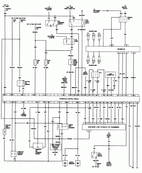
Diagrams of ignition wiring show the wiring used to supply power to different parts of the vehicle. Each part has four distinct color-coded connections. Red is used to indicate accessories, yellow is the battery, and green is the starter solenoid. The “IGN terminal is used for starting the car, controlling the wipers and various other functions. The diagram shows how to connect the ACC and ST terminals to the rest of the components.
The terminal BAT is the connection to the battery. The electrical system will not start without the battery. The switch also won’t turn on without the battery. To locate your car’s battery examine the wiring diagram. The accessory terminals of your car are connected to the battery and the ignition button. The BAT terminal connects to the battery.
Certain ignition switches provide an additional “accessory position” that allows users to alter their outputs without the ignition. Sometimes, customers want to make use of an additional output independent of the ignition. You can use the additional output by connecting it to an ACC terminal on the switch using the same colors. This is a great feature, however there’s one important distinction. A majority of ignition switches feature an ACC position when the car is in the ACC mode and a START mode when the switch is in IGN.
Gallery of S10 Ignition Wiring Diagram
Gallery of S10 Ignition Wiring Diagram


