Saab 900 Ignition Switch Wiring Diagram – We’ll begin by looking at the various kinds of terminals that are found on an ignition switch. The terminals are the Ignition switch, the Coil and the Accessory. After we’ve identified the purpose of these terminals, it is possible to determine the various components of the ignition wiring. We’ll also discuss the functions and the Coil. Then we’ll move on to the Accessory Terminals.
Terminals for the ignition switch
The ignition switch is comprised of three different switches that direct the battery’s current to various destinations. The choke is powered by the first switch. The third switch regulates the ON/OFF of the ignition switch. Different manufacturers have different colour-coding systems that correspond to the conductors. OMC utilizes this method. The ignition switch is also equipped with an adapter for the addition of a tachometer.
While many ignition switch terminals don’t have the original design The numbering might not be in line with the diagram. Check the continuity of all wires to ensure they are correctly plugged into the ignition switches. A multimeter is an excellent tool to check the continuity. Once you’ve verified the integrity of the wires you can connect the connector. If your car has an ignition switch that is installed the wiring diagram will differ.
Understanding how ACC outputs are connected to the auxiliary outputs in your car is essential. The ACC, IGN and START terminals are the default connections to the ignition switch. They also serve as the primary connections to your radio and stereo. The ignition switch turns the car’s engine ON and off. Older cars are identified with the alphabets “ACC”, “ST”, (for individual magneto cables) on their ignition switch terminals.
Terminals for Coil
Understanding the terms used is the first step to determining the kind of ignition coil you need. There are a variety of connections and terminals within the basic wiring diagram for ignition which includes two primary as well as two secondary. The voltage that operates on each coil differs. This is why it is crucial to test the voltage at the S1 (primary terminal). S1 must be examined for resistance to identify if the coil is type A, B or C.
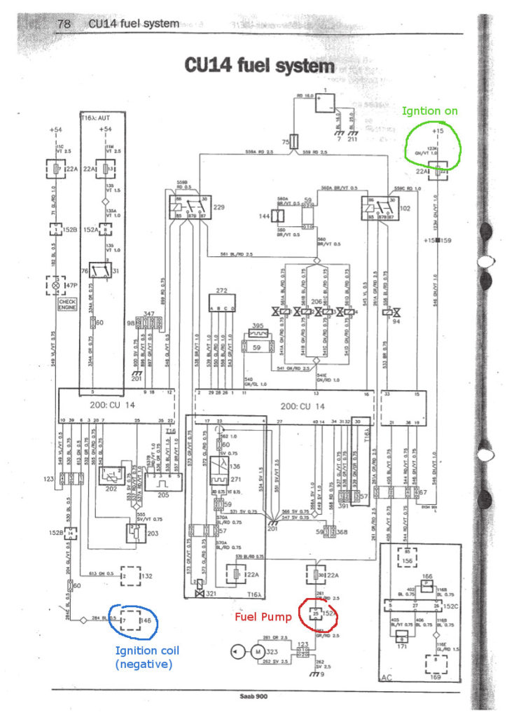
The chassis’ negative needs to be connected to the side of low-tension. This is what is known as the ground for the ignition wiring. The high-tension part supplies the spark plugs with positive. To reduce the noise, the coil’s body metal must be connected with the chassis. This is not necessary to use electricity. The ignition wiring diagram will also indicate the connection of the positive coil’s terminals. Sometimes, a malfunctioning ignition coil can be detected by a scan done at an auto parts shop.
The black-and-white-striped wire from the harness goes to the negative terminal. The terminal for the negative is served by the black trace that’s connected to the white wire. The black wire is connected to the contactbreaker. You can take the black wire from the housing of the plug using a paper clip If you’re unsure of the connections. Be sure the terminals don’t bend.
Accessory terminals
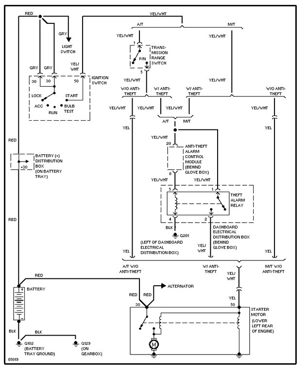
The ignition wiring diagrams show the different wires used to power the various components. In general, there are four different colors-coded terminals that are used for each component. To identify accessories, red is the starter solenoid’s color, yellow is for battery, and blue for accessory. The “IGN terminal” is used to power the wipers along with other operational functions. The below diagram shows how to connect the ACC terminal as well as the ST terminals to the other components.
The terminal BAT connects the battery to the charger. The electrical system won’t start if the battery isn’t connected. Additionally, the switch won’t begin to turn on. To locate your car’s battery look over your wiring diagram. The accessory terminals in your vehicle are connected to the battery as well as the ignition button. The BAT connector connects to your battery.
Some ignition switches are equipped with an additional position. This lets users access their outputs from a different location without the ignition. Some customers may prefer to utilize the auxiliary output independently of the ignition. To allow the auxiliary output to be used, plug in the connector in the same shade as that of the ignition. Then , connect it to the ACC end of the switch. This convenience feature is great, but there is one difference. Many ignition switches can be configured to be in an ACC position once the car is in the ACC position. They’ll also be in START mode when the vehicle has entered the IGN position.
Gallery of Saab 900 Ignition Switch Wiring Diagram
Gallery of Saab 900 Ignition Switch Wiring Diagram


