Sbc Ignition Wiring Diagram – We will first look at the various kinds and functions of terminals found on the ignition switches. These terminals comprise the Ignition switch as well as the Coil as well as the Accessory. Once we have identified the terminals used, we can begin to determine the various components of the Sbc Ignition Wiring Diagram. In addition, we will discuss the function of the Ignition switch, as well as the Coil. Following that, we’ll shift our attention to Accessory terminals.
Terminals for the ignition switch
An ignition switch is made up of three different switches. They are the ones that supply the battery’s power to several locations. The first switch provides power to the choke whenever it is pushed. The third is the switch that controls the ignition’s ON/OFF positions. Different manufacturers have different color-coding systems to identify different conductors. We will cover this in another article. OMC uses the same method. This connector allows the connection of a speedometer to the ignition switch.
While some ignition switch terminals do not have the original design, the numbering may not be in line with the diagram. Before plugging into the ignition switch, be sure to test the continuity. This can be accomplished using a simple multimeter. Once you’re satisfied about the integrity of your wires, you’ll be able install the new connector. If your car is equipped with an original factory-supplied ignition switch (or wiring loom), the wiring loom might differ from that of your car.
To connect the ACC outputs to the auxiliary outputs of your car, you need to understand how these two connections work. The ACC, IGN and START terminals are the default connection to the ignition switch. They are also the main connections to the radio and stereo. The ignition switch is accountable for turning the car’s engine on and off. Older vehicles are identified with the alphabets “ACC”, “ST”, (for individual magneto cables) at their ignition switch’s terminals.
Terminals for coil
Understanding the terms used is the initial step to determining the kind of ignition coil to choose. In a basic ignition wiring diagram, you will see several different terminals and connections, including two primary and two secondary. Each coil is operating at a certain voltage. The first step to determine the kind of coil you have is to check the voltage at S1 or the primary terminal. To determine if the coil is a Type A, C, or B coil you must also test S1’s resistance.
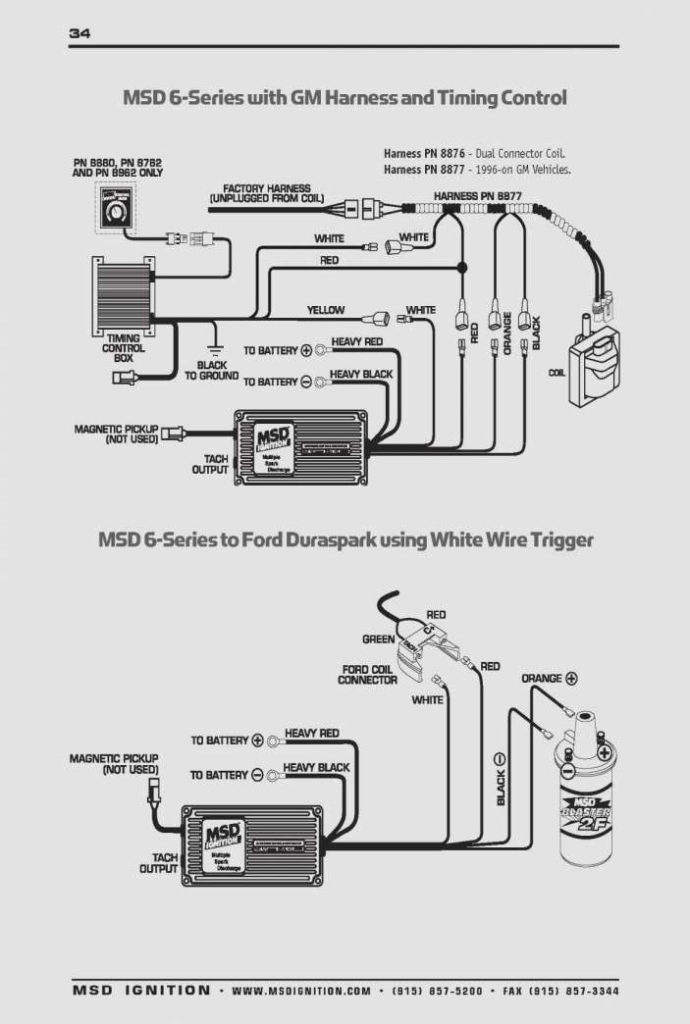
The lower-tension side of the coil needs to be connected to the chassis”negative. This is the ground of the wiring for ignition. The high tension side supplies positively directly to the spark plugs. The coil’s metal body needs to connect to the chassis to suppress the effect but is not electrically necessary. The ignition wiring diagram will also show the connection of the positive coil terminals. Sometimes, a malfunctioning ignition coil can be detected through a scan performed in an auto parts shop.
The black-and-white-striped wire from the harness goes to the negative terminal. The positive terminal is connected to the white wire and a trace of black. The black wire is connected to the contact breaker. It is possible to check the connections with a paperclip to take the wires out from the housing. It’s also crucial to ensure that the terminals aren’t bent.
Accessory terminals
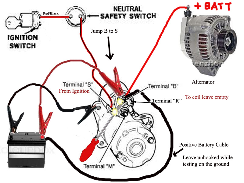
Diagrams of ignition wiring depict the wires used to power various parts of the vehicle. There are typically four color-coded terminals that correspond to each component. To identify accessories, red is the starter solenoid’s color, blue for battery and blue for accessories. The “IGN terminal allows you to start the car, manage the wipers, and any other features that operate. The below diagram shows how to connect the ACC terminal as well as the ST terminals to other components.
The battery is connected to the terminal whose name is BAT. Without the battery the electrical system can not start. In addition, the switch will not begin to turn on. To find your car’s battery look over your wiring diagram. The ignition switch as well as the battery are connected via accessory terminals. The BAT terminal is connected to the battery.
Some ignition switches come with an additional “accessory position” that lets users alter their outputs without the ignition. Sometimes, customers may wish to utilize the auxiliary output separately from the ignition. To allow the auxiliary output to be used, wire the connector to the same shade as the ignition. Then connect it with the ACC end of the switch. This is a great convenience feature, but there is one differentiator. The majority of ignition switches are set to have an ACC position when the vehicle is in the ACC position, while they’re in the START position when the vehicle is in the IGN position.
Gallery of Sbc Ignition Wiring Diagram
Gallery of Sbc Ignition Wiring Diagram


