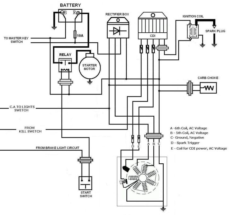
Scooter Ignition Wiring Diagram – Let’s first examine the different types and functions of the terminals that are found on the ignition switches. These include the terminals that are for the Ignition switch, Coil, and Accessory. After we’ve established what these kinds of terminals are used for, we will proceed to identify the different parts of the Scooter Ignition Wiring Diagram. We will also discuss the roles of the Ignition switch and the Coil. After that, we will concentrate on the accessory terminals.
Terminals for ignition switch
An ignition switch is composed of three switches. These are responsible for feeding the battery’s energy to various places. The first switch is the one that supplies the choke with power, while the second switch controls the status of the ignition switch. Different manufacturers have their own color-coding system for the different conductors, which is documented in another article. OMC uses this method. Connectors can be connected to the ignition switch in order to connect an electronic tachometer.
While the majority of ignition switch terminals don’t have an original number, they might have a different one. Before you plug in the ignition switch, ensure that you check the continuity. A multimeter is a good tool to test the continuity. When you’re satisfied that all wires are in good order and you are able to connect the new connector. If you’re using an ignition switch that is supplied by the manufacturer the wiring loom will be different from that you have in your car.
It is essential to know how the ACC outputs and the auxiliary outputs function in order to connect them. The ACC and IGN connectors are the standard connections for your ignition switch. The START, IGN, and ACC terminals are primary connections for the radio or stereo, the START/IGN connections are the primary ones. The ignition switch is responsible for turning the car’s engine to and off. Older vehicles have ignition switch terminals labeled “ACC” or “ST” (for individual magnetowires).
Terminals for coil
Understanding the terms is the first step to determining which type of ignition coil you have. A simple diagram of the wiring will reveal a variety of terminals and connections, including two primary and two secondaries. Each coil comes with its own operating voltage. To determine which type of coil you have, the first step is to check the voltage at S1, which is the primary terminal. S1 should also be checked for resistance to determine whether it’s an A, Type B, or an A coil.
The low-tension side of the coil must be connected to the chassis’ negative. This is also the ground for an ignition wiring diagram. The high tension part supplies positively directly to the spark plugs. It is necessary for the purpose of suppression that the coil’s metallic body be connected to the chassis, but not essential. A wiring diagram can also show the connection between the positive and negative coil terminals. There could be an issue with your ignition coil that is easily identified by scanning it in an auto parts retailer.
The black-and-white-striped wire from the harness goes to the negative terminal. The negative terminal is served by the black trace that’s attached to the white wire. The black wire connects to the contact breaker. You can take the black wire from the plug housing using a paper clip If you’re unsure of the connection. Make sure you ensure that the terminals have not been bent.
Accessory terminals
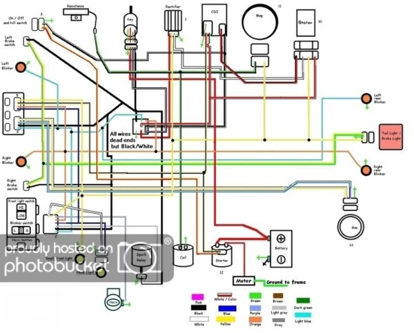
The ignition wiring diagrams show the different wires used to power the various components. There are generally four colored terminals for each component. The red symbol represents accessories, yellow is for the battery and green is for the starter solenoid. The “IGN terminal is used for starting the car, operating the wipers and other functions. The diagram demonstrates how to connect the ACC and ST terminals to the other components.
The terminal BAT is the connector for the battery. The electrical system can’t be started without the battery. Additionally, the switch will not start without the battery. You can refer to your wiring diagram if not sure where the batteries of your car are. The ignition switch and battery are connected by the accessory terminals. The BAT terminal is connected to the battery.
Some ignition switches come with an additional position. It allows users to access their outputs from a different location without having to turn on the ignition. In some cases, users may want to utilize the auxiliary input separately from the ignition. For the auxiliary output to be used, plug in the connector to the same color as that of the ignition. Then connect it with the ACC end of the switch. This is an excellent feature, but there is one important distinction. The majority of ignition switches are set to be in an ACC position when the vehicle is in the ACC position, whereas they’re set to the START position when the car is in the IGN position.
Gallery of Scooter Ignition Wiring Diagram
Gallery of Scooter Ignition Wiring Diagram


