Sierra Ignition Switch Mp39760 Wiring Diagram – Let’s first examine the different kinds and functions of terminals found in the ignition switches. They include terminals that are used for Coil, Ignition Switch, and Accessory. Once we’ve determined the function of the terminals we can recognize the various parts of the ignition wiring. We’ll also discuss the functions as well as the Coil. Then, we’ll talk about the function of the Ignition switch as well as Coil.
Terminals for ignition switches
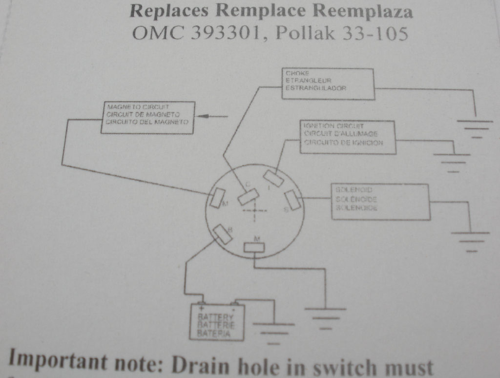
Three switches can be found on an ignition switch. Each of these switches is able to feed the battery’s voltage to several different places. The first switch supplies the choke with power, while the second toggles the on/off state of the switch. Different manufacturers employ different color codes for various conductors. This is described in a separate article. OMC follows this method. A connector is also included in the ignition switch for attaching an to a tachometer.
While the majority of ignition switch terminals don’t have an initial number, they could have a different one. To make sure that the wires are properly connected to the ignition switch, you must verify their continuity. This can be done using a simple multimeter. When you’re satisfied that the wires are in good continuity then you can connect the new connector. If your vehicle has an ignition switch installed the wiring diagram may differ.
It is important to understand the ways in which the ACC outputs and the auxiliary outputs function in order to join them. The ACC/IGN connections function as the default connection on the ignition switch. The START/IGN connections connect to the stereo or radio. The ignition switch is responsible to turn the car’s engines on and off. The terminals for the ignition switch on older cars are identified with the initials “ACC” and “ST” (for individual magneto wires).
Terminals for coil
Understanding the terminology used is the initial step in determining the type of ignition coil. The fundamental diagram of ignition wiring shows a number different connections and terminals. There are two primary and secondary connections. Each coil is equipped with a distinct operating voltage. To determine what kind of coil you have, the first step is to test the voltage at S1, the primary terminal. S1 must also go through resistance testing to determine if it is an A or B coil.
The lower-tension side of the coil must be connected to the chassis”negative. This is what’s called the ground on the wiring diagram for ignition. The high-tension part provides the spark plugs with positive. It is essential for suppression purposes that the metallic body of the coil is connected to its chassis, however it isn’t essential. The wiring diagram for ignition will also outline how to connect the positive coil’s terminals. Sometimes, a defective ignition coil can be detected through a scan performed in an auto parts shop.
The black-and-white-striped wire from the harness goes to the negative terminal. The terminal for the negative is served by the trace in black that’s attached to the white wire. The black wire is connected to the contact breaker. To verify the connections, you can employ a paperclip, or a pencil to pull them out from the plug housing. Be sure to verify that the connections have not been bent.
Accessory terminals
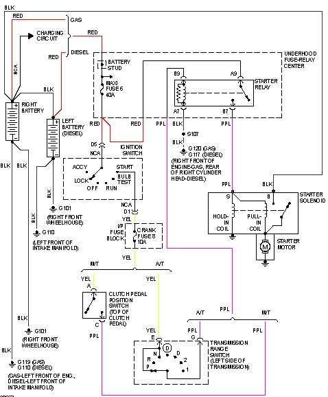
Ignition wiring diagrams show the various wires utilized to power the vehicle’s various parts. There are generally four colored terminus lines for each component. The red symbol represents accessories, yellow is for the battery and green is for the starter solenoid. The “IGN terminal allows you to start the car, manage the wipers, or any other functions. This diagram shows how you can connect ACC and ST terminals with the rest of the components.
The terminal BAT is the connector for the battery. The electrical system will not start if the battery isn’t connected. Additionally, the switch will not turn on without the battery. A wiring diagram can inform you the location of your car’s battery. The accessory terminals of your car are connected to the battery and the ignition switch. The BAT terminal is connected to the battery.
Certain ignition switches have an additional position in which users can adjust their outputs as well as control them without needing to use the ignition. Some customers prefer to utilize an additional output independent of the ignition. Make use of the secondary output by connecting it to an ACC terminal on the switch using the same colors. While this is an excellent option, there’s a thing to be aware of. The majority of ignition switches are set to have an ACC position when the car is in the ACC position, while they’re in the START position when the vehicle is in the IGN position.
Gallery of Sierra Ignition Switch Mp39760 Wiring Diagram

Gallery of Sierra Ignition Switch Mp39760 Wiring Diagram


