Sierra Mp41070 2 Ignition Switch Wiring Diagram – First, let’s examine the various terminals on the ignition switch. These terminals comprise the Ignition switch as well as the Coil and the Accessory. After we’ve identified what these terminals are, we will identify the different parts in the ignition wiring. We’ll also discuss the functions of the Ignition switch and Coil. The next step is to focus to the accessory terminals.
Terminals for ignition switches
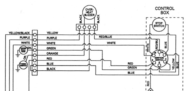
An ignition switch has three switches. They transmit the battery’s voltage to different locations. The first switch provides power to the choke whenever it is pushed. The third is the switch that controls the ignition’s ON/OFF positions. Every manufacturer has its individual color-coding system that we will discuss in another article. OMC uses the same method. An additional connector is included in the ignition switch for connecting the Tachometer.
Although the majority of ignition switch terminals are duplicated, the numbers may not match the diagram. Before you plug into the ignition switch ensure that you check the continuity. You can check this using an inexpensive multimeter. When you’re satisfied with the continuity of your wires, you will be able install the new connector. If your car has an original factory-supplied ignition switch (or an electrical loom), the wiring loom will differ from that in the car.
The first step is to understand the distinctions between ACC and the auxiliary outputs. The ACC/IGN connections function as the default connections on the ignition switch. The START/IGN terminals are connected to the stereo or radio. The ignition switch is responsible for turning the car’s engine on and off. On older vehicles the ignition switch’s terminals are marked with the initials “ACC”, and “ST” (for distinct magnetic wires).
Terminals for coil
Understanding the terminology is the initial step towards finding out what kind of ignition coil you have. A basic ignition wiring diagram will reveal a variety of terminals and connections comprising two primary and two secondaries. Each coil has a specific operating voltage. To determine what kind of coil you own first, you need to determine the voltage at the S1 primary terminal. S1 should be examined for resistance to determine if the coil is type A, B or C.
The chassis’ negative must be connected to the coil’s low-tension side. It is also the ground in the diagram of ignition wiring. The high-tension part provides the spark plugs with positive. The coil’s metal body needs to connect to the chassis to suppress the effect however it isn’t electrically necessary. There are also connections of the positive and negative coil terminals on the diagram of the ignition wiring. Sometimes, a damaged ignition coil can be detected by a scan done at an auto parts shop.
The black-and-white-striped wire from the harness goes to the negative terminal. The positive terminal also receives a white wire that is black in its trace. The black wire connects to the contactbreaker. If you’re not sure about the connections between the two, try using the clip of a paperclip to remove them from the plug housing. Be sure to verify that the connections have not been bent.
Accessory terminals
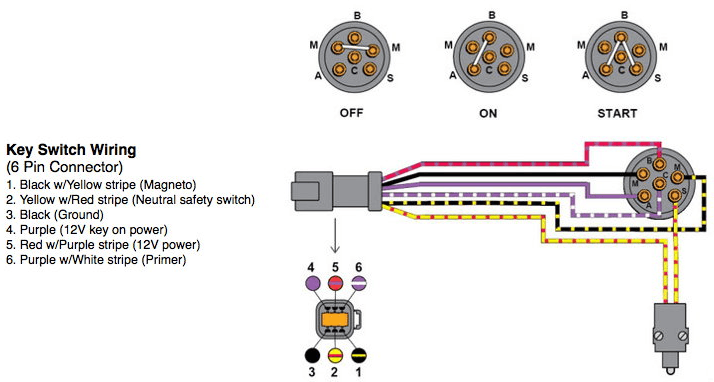
The ignition wiring diagrams show the various wires utilized for powering the different components. There are usually four color-coded terminus for each component. The red color is for accessories, yellow the battery and green for the starter solenoid. The “IGN terminal is used to start the car, operating the wipers, and for other functions. The diagram shows the connections between the ACCas well as ST terminals.
The terminal BAT connects the battery to the charger. The electrical system won’t start if the battery isn’t connected. The switch won’t be able to turn off if the battery isn’t there. The wiring diagram will show the location of the battery in your car. The accessory terminals in your vehicle are connected to the battery as well as the ignition button. The BAT Terminal is connected to the Battery.
Some ignition switches come with a separate “accessory” location, which allows users can control their outputs with no ignition. Some customers prefer to make use of an additional output that is independent of the ignition. To make use of the additional output, wire the connector using the same colors as ignition, connecting it to the ACC terminal on the switch. This is a great feature, however there’s one important distinction. The majority of ignition switches are set to operate in the ACC position when the car is in the ACC position, while they’re set to the START position when the vehicle is in the IGN position.
Gallery of Sierra Mp41070 2 Ignition Switch Wiring Diagram
Gallery of Sierra Mp41070 2 Ignition Switch Wiring Diagram


