Simple Ignition Switch Wiring Diagram – Let’s first take a look at the different types of terminals used on the ignition switch. These include the terminals that are for the Ignition switch, Coil, and Accessory. Once we have established what these types of terminals are used for then we can discover the various components of the Simple Ignition Switch Wiring Diagram. In addition, we will discuss the roles of both the Ignition Switch and the Coil. We will then concentrate on the accessory terminals.
Terminals of ignition switch
There are three switches on the ignition switch, and they feed the battery’s voltage to several different locations. The ON/OFF position of the switch that controls the ignition is managed by the second switch, which delivers power to the choke whenever it’s pushed. Different manufacturers use different color-coding systems that correspond to the conductors. OMC follows this system. Connectors can be connected to the ignition switch in order to add an electronic Tachometer.
Although the majority of ignition switch terminals are duplicated, the number may not match the diagram. First, check the continuity of each wire to ensure they are correctly plugged into the ignition switches. A multimeter is an excellent tool to check the continuity. After you’re sure that all wires are running in good harmony, you can attach the new connector. The wiring loom of an ignition switch that’s factory-supplied will be different than the one you have in your car.
Understanding how the ACC outputs connect to the auxiliary outputs of your car is vital. The ACC, IGN and START terminals are the primary connections to the ignition switch. They are also the main connections to the radio and stereo. The ignition switch controls the car’s engine. The terminals for the ignition switch on older cars are identified with the alphabets “ACC” as well as “ST” (for individual magneto wires).
Terminals for coil
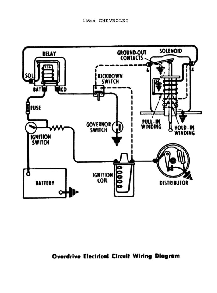
Understanding the terms is the initial step to determining which type of ignition coil you have. An understanding of the basic wiring diagram for ignition will reveal a variety of terminals and connections. You must determine the kind of coil you have by testing the voltage on the primary terminal S1. To determine whether it’s an A, C or B coil you should also check the resistance of S1.
The negative of the chassis must be connected to the low-tension side. This is also the ground for an ignition wiring diagram. The high-tension side delivers positively directly to the spark plugs. The body of the coil has to connect to the chassis to suppress the effect however it isn’t electrically necessary. There are also connections of the positive and the negative coil terminals on the ignition wiring diagram. Sometimes, a check at an auto parts store could identify a problem with the ignition wire.
The black-and-white-striped wire from the harness goes to the negative terminal. Positive terminal receives the white wire that has a black trace. The black wire is connected to the contactbreaker. You can remove the black wire from the housing of the plug using a paper clip if you are unsure about the connection. It is also important to ensure that the terminals are not bent.
Accessory Terminals
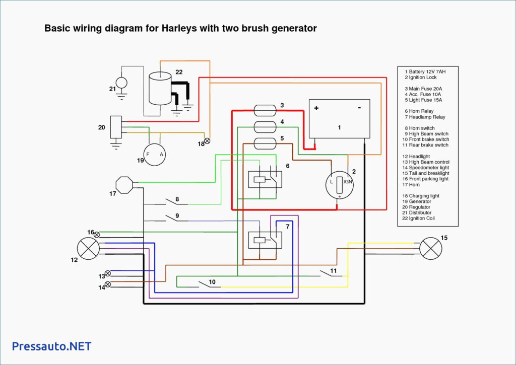
Diagrams of ignition wiring show the wiring used to power the vehicle’s electrical supply. Each component is equipped with four distinct color-coded connections. Red refers to accessories, yellow to the battery, and green for the starter solenoid. The “IGN” terminal is used to turn on the vehicle and control the wipers and other operating features. The diagram illustrates the connection between the ACC- and ST terminals.
The terminal called BAT is the place where the battery is. The battery is essential for the electrical system to begin. Also, the switch won’t start without the battery. The wiring diagram will inform you where to find the battery of your car. Your car’s accessory terminals are connected to the ignition switch and the battery. The BAT terminal is connected with the battery.
Some ignition switches come with an additional position. This lets users access their outputs from another location without the ignition. Users may wish to use the auxiliary output independently of the ignition. To allow the auxiliary output to be used, plug in the connector with the same color as the ignition. Then , connect it to the ACC end of the switch. This is a great convenience feature however, there’s one differentiator. Most ignition switches come with an ACC position when your vehicle is in ACC mode and a START mode when the switch is in IGN.
Gallery of Simple Ignition Switch Wiring Diagram
Gallery of Simple Ignition Switch Wiring Diagram


