Small Engine Ignition Coil Wiring Diagram – The first step is to examine the various terminals that are used in the ignition switch. These terminals are used for the Ignition button, Coil and Accessory. Once we know the terminals used and which ones are not, we can recognize the various parts of the Small Engine Ignition Coil Wiring Diagram. We will also discuss the functions of the Ignition switch and Coil. The next step is to focus to the accessory terminals.
The terminals are for ignition switches.
There are three switches in an ignition switch that transmit the battery’s current voltage to various locations. The first switch supplies the choke with power, while the second toggles the on/off status of the ignition switch. Every manufacturer has its unique color-coding system, which we’ll discuss in a subsequent article. OMC utilizes this system. Connectors can be attached to the ignition switch to include the digital Tachometer.
While many ignition switch terminals could not be original, the numbering of the terminals may not be in line with the diagram. Before you plug into the ignition switch, make sure to check the continuity. A multimeter that is inexpensive can assist you in this. When you’re happy with the connection, you can place the new connector. If your car is equipped with an original ignition switch supplied by the factory (or a wiring loom) the wiring loom might differ from the one in the car.
To connect the ACC outputs to the auxiliary outputs of your car, you need first know the way these two connections function. The ACC and IGN terminals are the default connections on your ignition switch. the START and IGN terminals are the main connections for radio and stereo. The ignition switch switches the car’s engine ON and off. Older cars are equipped with ignition switch terminals labeled “ACC” or “ST” (for individual magnetowires).
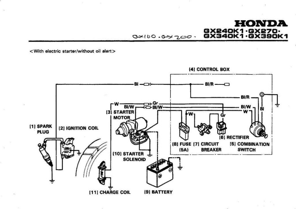
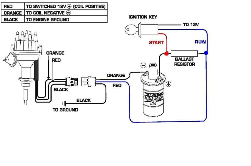
Coil terminals
To determine the type of ignition coil, the first step is to know the terms. There are a variety of connections and terminals within an ignition wiring schematic which includes two primary and two secondary. The voltage that operates on each coil differs. This is why it is important to first test the voltage at S1 (primary terminal). S1 must be tested for resistance in order to determine if the coil is Type A, B, or C.
The coil with low tension must be connected to the chassis’ plus. This is also the ground on the ignition wiring diagram. The high-tension part supplies positive direct to the sparkplugs. The coil’s aluminum body needs to be connected to the chassis for suppression but isn’t required. A wiring diagram can also show the connection between the positive and negative coils. It is possible to find an issue with the ignition coil that is easily identified by looking it up at an auto parts store.
The black-and-white-striped wire from the harness goes to the negative terminal. The white wire is black-colored and goes to the negative terminal. The black wire is connected to the contact breaker. To check the connection, employ a paperclip, or a pencil to remove them of the housing for the plug. It is also important to make sure that the connections are not bent.
Accessory Terminals
The wiring diagrams for the ignition show the various wires that power the various components of the vehicle. Each component has four distinct colored connections. To identify accessories, red stands for starter solenoid, yellow is for battery and blue for accessory. The “IGN terminal is used for starting the car, operating the wipers, and for other functions. This diagram shows how to connect ACC and ST terminals to the rest of components.
The terminal BAT connects the battery to the charger. The electrical system is not able to begin without the battery. The switch will not turn off if the battery isn’t present. If you’re not sure of the exact location where the battery in your car is situated, review the wiring diagram of your car to determine how to locate it. The accessory terminals of your car are connected to the battery as well as the ignition switch. The BAT terminal is connected to the battery.
Certain ignition switches have a separate “accessory” position, where users can manage their outputs with no ignition. Customers may want to utilize the auxiliary output independently of the ignition. In order to use the auxiliary output, wire the connector with identical colors to the ignition, and connect it to the ACC terminal on the switch. Although this is a fantastic feature, there’s one thing you should know. Most ignition switches are configured to be in an ACC position when the car is in the ACC position, but they’re set to the START position when the vehicle is in the IGN position.
Gallery of Small Engine Ignition Coil Wiring Diagram
Gallery of Small Engine Ignition Coil Wiring Diagram


