Small Engine Ignition Switch Wiring Diagram – We’ll begin by looking at the different types of terminals on an ignition switch. These are terminals for the Ignition, Coil, or Accessory. Once we know the terminals used, we can begin to determine the various components of the Small Engine Ignition Switch Wiring Diagram. We’ll also go over the roles of the Ignition switch and Coil. After that, we will turn our attention towards the accessories terminals.
Terminals for the ignition switch
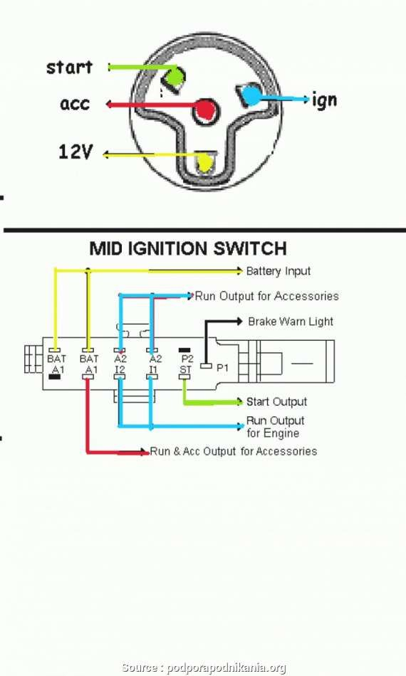
The ignition switch is comprised of three switches that supply the battery’s current to various destinations. The first switch powers the choke. The second switch is responsible for the ON/OFF function of the ignition switch. Different manufacturers use different color-coding methods for different conductors. We’ll discuss this in a different article. OMC follows this method. The ignition switch also includes a connector for adding an Tachometer.
Although the majority of ignition switch terminals are not original, the numbering for each might not be consistent with the diagram. To make sure that the wires are plugged in to the switch, you must verify their continuity. A multimeter is a great instrument to verify the continuity. After you have verified the integrity of the wires you are able to install the connector. The wiring loom in the ignition system switch supplied by the manufacturer is different.
First, understand the differences between ACC and secondary outputs. The ACC/IGN connections function as the default connections for the ignition switch. The START/IGN connections connect to the radio or stereo. The ignition switch is accountable for turning the car’s engine on and off. On older cars the ignition switch’s terminals are identified with the letters “ACC”, and “ST” (for individual magnet wires).
Terminals for coil
The terms used to define the type and model of an ignition coil is the most important thing. A basic ignition wiring layout will provide you with a range of connections and terminals. The coils have a specific operating voltage. The first step in determining which type you’ve got is to check the voltage on S1, the primary terminal. S1 must be checked for resistance to determine if the coil belongs to type A, B or C.
The coil’s low-tension side should be connected at the chassis’s less. This is the wiring diagram you will see in the diagram of wiring. The high tension side supplies positive power directly to the spark plugs. The coil’s aluminum body needs to be connected to the chassis for suppression however it’s not electrically required. You will also see the connections of the positive and the negative coil terminals on the ignition wiring diagram. Sometimes, a visit to an auto part store can detect a defective ignition wire.
The black-and-white-striped wire from the harness goes to the negative terminal. The positive terminal receives the other white wire with the trace in black. The black wire is connected to the contact breaker. You can examine the connections with a paperclip to pull the wires out from the housing. Make sure that the terminals don’t bend.
Accessory terminals
The wiring diagrams for the ignition show the various wires that provide power to the various parts of the car. Each component has four distinct connections that are color coded. Red stands for accessories, yellow represents the battery and green for the starter solenoid. The “IGN” terminal is used to turn on the car and operate the wipers and other operating functions. The following diagram shows how to connect both the ACC terminal and ST terminals to various components.
The terminal BAT holds the battery. The battery is essential for the electrical system to start. The switch won’t be able to turn on if the battery isn’t there. It is possible to look up your wiring diagram to determine the location of your car’s batteries. situated. The ignition switch as well as the battery are connected through the accessory terminals. The BAT Terminal is connected to the battery.
Some ignition switches are equipped with an accessory position. It allows users to connect their outputs to a different location without having to turn on the ignition. Sometimes, users want to make use of an additional output that is not connected to the ignition. The auxiliary output can be used to connect the connector with the same colors as your ignition, and then attaching it to the ACC terminal of the switch. While this is a convenient feature, there is one important difference. Most ignition switches are set to have an ACC position when the vehicle is in the ACC position, whereas they’re set to the START position when the car is in the IGN position.
Gallery of Small Engine Ignition Switch Wiring Diagram
Gallery of Small Engine Ignition Switch Wiring Diagram


