Snapper Ignition Switch Wiring Diagram – Let’s begin by looking at the different types terminals found on an ignition switch. These terminals are for the Ignition button, Coil and Accessory. Once we know the terminals that are utilized and which ones are not, we can identify the different components of the Snapper Ignition Switch Wiring Diagram. We will also discuss the functions of the Ignition switch and Coil. Then, we’ll focus to the accessory terminals.
Terminals of ignition switch
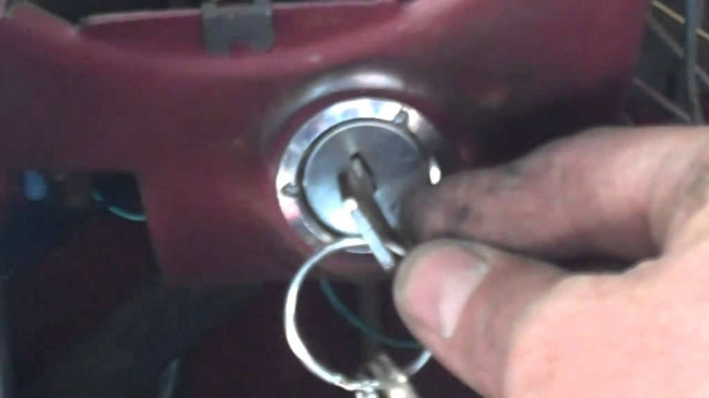
There are three different switches on an ignition switch that transmit the battery’s current voltage to several different destinations. The ON/OFF position of the switch that controls the ignition is managed by the second switch, which provides the choke with power when it is pushed. Different manufacturers have distinct colors-coding systems to match the conductors. OMC follows this system. A connector can be added to the ignition switch in order to add an electronic tachometer.
While most ignition switch terminals can be duplicated, the numbers might not be in line with the diagram. To make sure that the wires are connected to the switch, you must verify their continuity. You can check this using a simple multimeter. After you’re happy with the continuity of the wires, then you’ll be able install the new connector. If your vehicle is equipped with an ignition switch that is installed the wiring diagram will differ.
Before you can connect the ACC outputs to your car’s auxiliary outputs it is crucial to be familiar with the fundamentals of these connections. The ACC/IGN terminals act as the default connections on the ignition switch. The START/IGN terminals are connected to the stereo or radio. The ignition switch is the one that controls the engine of your car. The terminals of older cars’ ignition switches are labeled by “ACC” and ST (for specific magneto wires).
Coil terminals
The first step to determine the kind of ignition coil is to know the terminology employed. You’ll see a number of connections and terminals on an ignition wiring schematic that include two primary as well as two secondary. Each coil operates at a specific voltage. The first step in determining which kind of coil you have is to check the voltage of S1 or the primary terminal. S1 must be tested for resistance in order to determine if the coil belongs to Type A, B, and/or C.
The chassis’ negative needs to be connected to the low-tension side. This is also the ground in the diagram of ignition wiring. The high-tension side connects the spark plugs to a positive. The aluminum body of the coil needs to be connected to the chassis for suppression but isn’t required. The ignition wiring diagram will also reveal how to connect the negative and positive coil’s terminals. Sometimes, a visit to an auto part store can detect a defective ignition wire.
The black-and-white-striped wire from the harness goes to the negative terminal. The terminal that is negative is served by the black trace that’s attached to the white wire. The contact breaker is connected to the black wire. To check the wires’ connections use a paperclip to lift them from the housing. Also, make sure to verify that the connections aren’t bent.
Accessory terminals
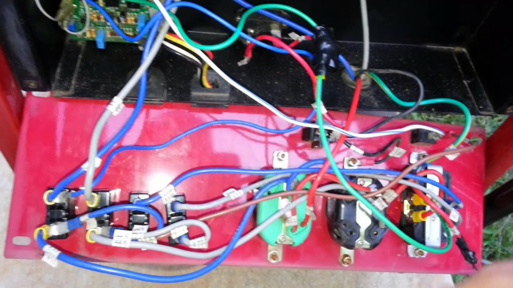
Diagrams of ignition wiring illustrate the wires used to provide power to various components of the car. There are usually four different colored terminals for each component. For accessories, red is for starter solenoid, yellow for battery, and blue for accessory. The “IGN” terminal is used to turn on the car , and also to operate the wipers, as well as other operating features. This diagram demonstrates how to connect ACC and ST terminals with the rest of components.
The terminal BAT is where the battery is. Without the battery the electrical system will not get started. In addition, the switch will not begin to turn on. A wiring diagram can inform you the location of the battery in your car. The ignition switch is connected to the battery of your car. The BAT connector is connected to the battery.
Some ignition switches have an “accessory” position that permits users to regulate their outputs without needing to utilize the ignition. Some customers may prefer to use the auxiliary output independently of the ignition. In order to use the auxiliary output, connect the connector in the same colors as ignition and connect it to the ACC terminal on the switch. This convenience feature is great however, there’s one differentiator. Most ignition switches are configured to have an ACC status when the vehicle is at either the ACC or START positions.
Gallery of Snapper Ignition Switch Wiring Diagram
Gallery of Snapper Ignition Switch Wiring Diagram


