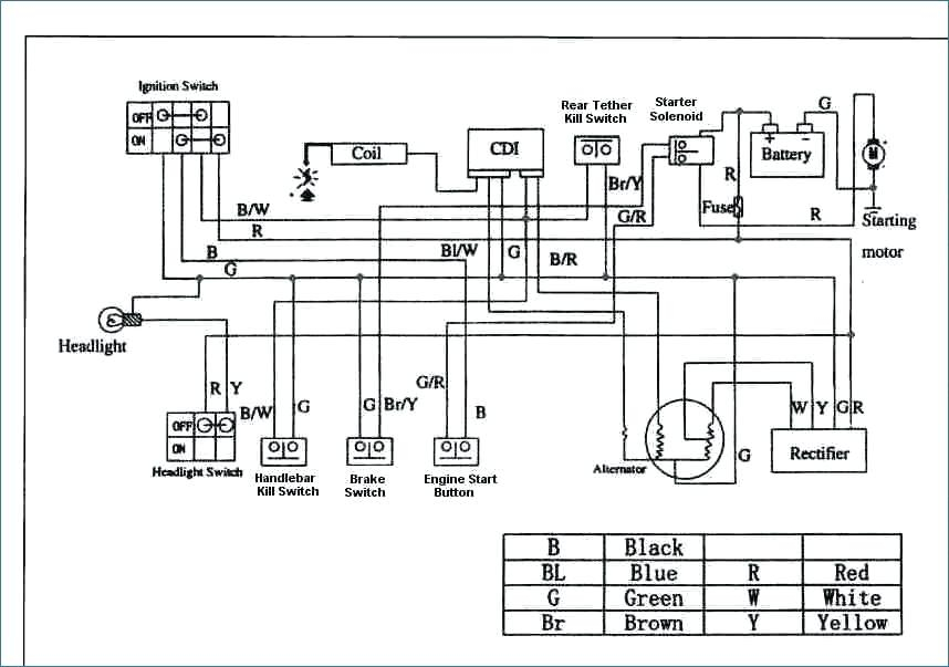
Taotao 50cc Scooter Ignition Wiring Diagram – We will first examine the different types of terminals for the ignition switch. These are terminals for the Ignition, Coil, or Accessory. Once we know the purpose of each type of terminal, we are able to identify the parts of the ignition wiring. We will also discuss the roles of the Ignition switch and Coil. We’ll then turn our attention to the accessory terminals.
Terminals for ignition switch
An ignition switch is comprised of three switches. They feed the battery’s voltage to many different places. The first switch supplies power to the choke, while the second toggles the state of the switch. Different manufacturers use different color codes for different conductors. This is discussed in a separate article. OMC follows this system. The connector allows for the attachment of a speedometer the ignition switch.
Although the majority of ignition switch terminals are not authentic, the numbering of each may not match the diagram. First, check the continuity of all wires to make sure they’re properly connected to the ignition switches. This can be accomplished using a cheap multimeter. When you’re happy with the continuity, you can place the new connector. If your vehicle has an original ignition switch supplied by the factory (or a wiring loom), the wiring loom may differ from that of your vehicle.
To connect the ACC outputs to the auxiliary outputs on your car, you’ll need to first understand how these two connections work. The ACC terminals as well as the IGN terminals are the primary connections to your ignition switch. The START and IGN connections are the main connections for radio and stereo. The ignition switch is the one that controls the engine of your car. Older cars are identified with the alphabets “ACC”, “ST”, (for individual magneto cables) at their ignition switch terminals.
Coil terminals
Understanding the terminology that is used is the first step in determining the type of ignition coil. A basic ignition wiring layout will provide you with a range of terminals and connections. The coils come with a distinct operating voltage. The first step to determine which one you’ve got is to check the voltage on S1, the main terminal. It is also recommended to check S1 for resistance to determine whether it is a Type A or B coil.
The negative of the chassis must be connected to the low-tension side. This is the ground on the ignition wiring diagram. The high tension side provides positively directly to the spark plugs. The aluminum body of the coil needs to be connected to the chassis for suppression however it’s not electrically required. The ignition wiring diagram will also outline the connection of the positive coil terminals. Sometimes, a damaged ignition coil is identified with a scan at an auto parts shop.
The black-and-white-striped wire from the harness goes to the negative terminal. The positive terminal receives the other white wire, which has an trace in black. The black wire is connected to the contactbreaker. To verify the connections, you can make use of a paperclip or pencil to remove them of the plug housing. Be sure the terminals do not bend.
Accessory terminals
Diagrams of ignition wiring illustrate the wires used in the power supply of the vehicle. There are generally four color-coded terminals that correspond to each component. For accessories, red stands the starter solenoid’s color, yellow is for battery, and blue is for accessory. The “IGN” terminal can be utilized to turn on the car, operate the wipers, as well as other functions. The diagram below illustrates how to connect the ACC terminal as well as the ST terminals to the other components.
The battery is connected to the terminal whose name is BAT. The electrical system will not start in the event that the battery isn’t connected. The switch also won’t start without the battery. You can refer to your wiring diagram if uncertain about where the car’s batteries are. The ignition switch as well as the battery are connected by the accessory terminals. The BAT terminal is connected to the battery.
Some ignition switches are equipped with an accessory position. It allows users to access their outputs from a different location without the ignition. Sometimes, customers wish to use the auxiliary output separately from the ignition. You can use the secondary input by connecting the connector to the ACC terminal. While this is a convenient feature, there is one important difference. Most ignition switches come with an ACC position when your vehicle is in ACC mode and a START mode when it is in IGN.
Gallery of Taotao 50cc Scooter Ignition Wiring Diagram
Gallery of Taotao 50cc Scooter Ignition Wiring Diagram


