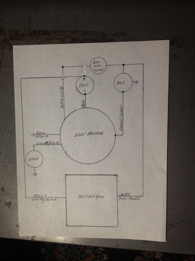
Ultima Digital Ignition System 53-644 Wiring Diagram – Let’s start by looking at the various types terminals found in an ignition switch. These terminals are used for the Ignition button, Coil and Accessory. Once we’ve determined the function of these terminals, we will be able to identify the various parts of the ignition wiring. We’ll also go over the functions for the Ignition switch and the Coil. We will then concentrate on the accessories terminals.
Terminals for ignition switch
The ignition switch has three switches. They transmit the voltage of the battery to different locations. The first switch powers the choke. The second switch controls the ON/OFF of the ignition switch. Different manufacturers have different color codes for various conductors. This is explained in another article. OMC uses this method. The adapter is attached to the ignition switch to allow the installation of a Tachometer.
Although the majority of ignition switch terminals can be duplicated, the number may not match the diagram. It is important to first verify the electrical continuity to determine if they’re plugged into the ignition switch correctly. A multimeter that is inexpensive can help you do this. After you have verified the integrity of the wires you are able to connect the connector. If you are using a factory-supplied ignition switch, the wiring loom is distinct from the one that is in your car.
It is important to understand the way that ACC outputs and the auxiliary outputs work in order to connect them. The ACC, IGN and START terminals are the primary connections to the ignition switch. They also function as the main connections to the radio and stereo. The ignition switch is responsible for turning the engine of your car to and off. Older cars are equipped with ignition switch terminals marked “ACC” or “ST” (for individual magnetowires).
Terminals for Coil
The terminology used to determine the kind and model of an ignition coil is the first thing. The diagram of the basic ignition wiring shows a number different connections and terminals. There are two primary and one secondary. The coils come with a distinct operating voltage, and the first step to determine which one you’ve got is to check the voltage of S1 the primary terminal. S1 should be tested for resistance in order to determine if the coil belongs to type A, B or C.
The chassis’ negative needs to be connected to the low-tension side. This is what’s called the ground in the ignition wiring diagram. The high-tension side is a positive connection to the sparkplugs. For suppression purposes, the coil’s metal body is required to be connected to the chassis. It is not necessary to connect the coil electrically. The ignition wiring diagram will also outline the connections of the positive coil’s terminals. In certain cases, a scan at your local auto parts store will help identify malfunctioning ignition coils.
The black-and-white-striped wire from the harness goes to the negative terminal. The terminal for the negative is served by the black trace that’s attached to the white wire. The black wire is connected to the contactbreaker. If you’re unsure of the connections between both, you can use the clip of a paperclip to remove them from the plug housing. Be sure the terminals don’t bend.
Accessory terminals
Diagrams of the ignition wiring show the wires that provide power to various components of the vehicle. There are typically four different colored terminus lines for each component. Red is used to indicate accessories, yellow the battery and green is the starter solenoid. The “IGN” terminal can be utilized to turn on the car, control the wipers, and other features. The diagram shows the connection between the ACCand ST terminals.
The terminal BAT is where the battery is. The electrical system won’t start without the battery. The switch will not turn on if the battery isn’t present. If you don’t know the exact location where the battery in your car is situated, look at your wiring diagram to see where it is. The ignition switch is connected to the battery of your car. The BAT connector is connected to your battery.
Some ignition switches come with the option of an “accessory position” that allows users to alter their outputs without the ignition. Sometimes, a customer wants to utilize the auxiliary output separately from the ignition. The auxiliary output could be connected by wiring the connector in the same colors as the ignition and attaching it to the ACC terminal of the switch. While this is a convenient feature, there is one important difference. Most ignition switches are set up to display an ACC status when the vehicle is in the ACC or START position.
Gallery of Ultima Digital Ignition System 53-644 Wiring Diagram
Gallery of Ultima Digital Ignition System 53-644 Wiring Diagram


