Ultima Ignition Module Wiring Diagram – Let’s begin by looking at the different kinds of terminals that are found in an ignition switch. These are the terminals for the Ignition, Coil, or Accessory. Once we know the purpose of each kind of terminal, we are able to identify the various components of the ignition wiring. Then, we will discuss the roles of the Ignition switch as well as the Coil. Following that, we’ll shift our attention to Accessory terminals.
Terminals for ignition switches
The ignition switch is comprised of three switches that supply the battery’s current to various locations. The first switch is used to turn on the choke through pushing it, and another switch controls the ON/OFF position. Different manufacturers use different color-coding methods for different conductors. We’ll discuss this in a separate article. OMC uses the same method. The ignition switch also includes an adapter for the addition of the Tachometer.
Even though most ignition switch terminals do not have an original number, they might be equipped with a different number. Before you plug in the ignition switch, make sure to check the continuity. This can be accomplished using a simple multimeter. Once you are satisfied with the continuity of the wires, connect the new connector. If your vehicle has an ignition switch that is installed the wiring diagram may differ.
You must first understand the way that ACC outputs and the auxiliary outputs function in order to join them. The ACC, IGN and START terminals are the default connections to the ignition switch. They also serve as the primary connections to your radio and stereo. The ignition switch controls the car’s engine. In older vehicles, the ignition switch terminals are identified with the alphabets “ACC” as well as “ST” (for distinct magnet wires).
Coil terminals
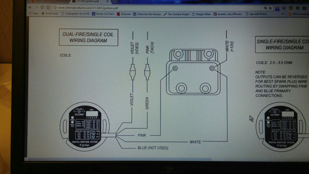
The language used to decide the type and model of the ignition coil is the first thing. The diagram of the basic ignition wiring illustrates a variety of connections and terminals. There are two primary and secondary connections. You must determine the kind of coil you own by examining the voltage on the primary terminal S1. S1 should also be tested for resistance in order to identify if it’s an A, Type B or A coil.
The coil’s low-tension side should be connected at the chassis’ plus. This is the wiring diagram you will see on the diagram of wiring. The high-tension component connects the spark plugs to a positive. To reduce the noise the body of the coil must be connected to chassis. However, it is not necessary to electrically connect. A wiring diagram can also illustrate the connection between the positive and negative coil terminals. It is possible to find an issue with your ignition coil which can be identified by scanning it in an auto parts store.
The black-and-white-striped wire from the harness goes to the negative terminal. The other white wire is black-colored and goes to the negative terminal. The black wire connects to the contact breaker. To confirm the connections, make use of a paperclip or pencil to pull them out from the plug housing. Make sure that the terminals aren’t bent.
Accessory Terminals
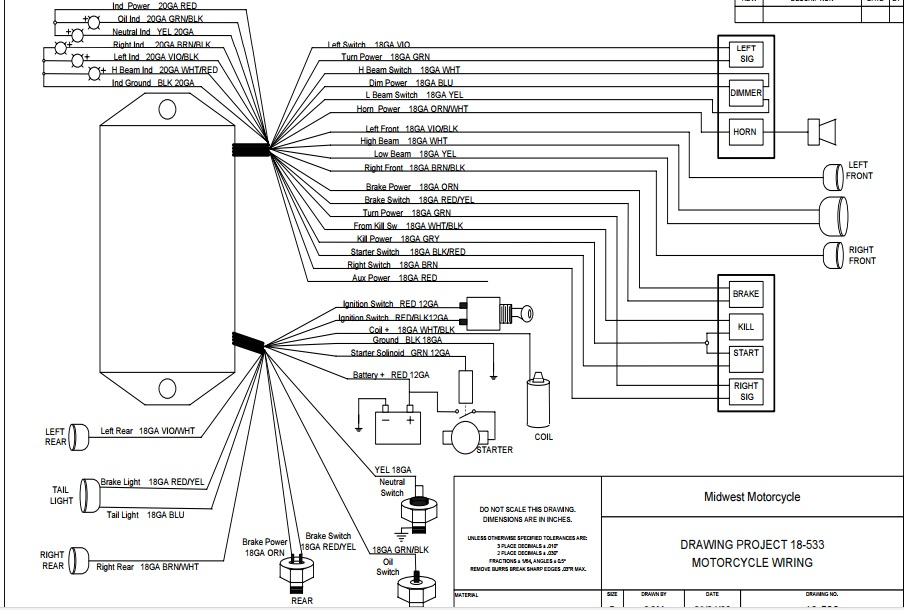
Ignition wiring diagrams show the different wires that are utilized to power the vehicle’s various components. There are typically four color-coded terminals that correspond to the respective component. Red is used to indicate accessories, yellow to the battery and green the starter solenoid. The “IGN terminal” is used to power the wipers as well as other operating features. The diagram shows how to connect ACC or ST terminals as well as the rest.
The terminal BAT is where the battery is. The electrical system is not able to start without the battery. Additionally, the switch will not turn on without the battery. You can view your wiring diagram to figure out where your car’s batteries are placed. The ignition switch and the battery are connected via accessory terminals. The BAT connector is connected to the battery.
Certain ignition switches have an additional position. This allows users to access their outputs from a different location without having to turn on the ignition. Some customers might want to utilize the auxiliary input independently of the ignition. For the auxiliary output to be used, plug in the connector to the same shade as that of the ignition. Then , connect it to the ACC end of the switch. This option is useful however, it does have one major distinction. Most ignition switches will be in an ACC position if the car is in the ACC, but they’ll be at the START position if the car is in IGN.
Gallery of Ultima Ignition Module Wiring Diagram
Gallery of Ultima Ignition Module Wiring Diagram


