Universal 4 Pole Ignition Switch Wiring Diagram – Let’s first examine the different types and purposes of the terminals in the ignition switches. These include the terminals that are for the Ignition switch, Coil, and Accessory. Once we have identified the purpose of these terminals, we will determine the various components in the ignition wiring. We’ll also go over the roles of the Ignition switch and the Coil. Following that, we’ll shift our attention to Accessory terminals.
Terminals for ignition switches
An ignition switch has three switches. They feed the battery’s voltage to many different places. The first switch supplies power to the choke whenever it is pushed. The second is the ignition switch’s ON/OFF position. Different manufacturers have different color-coding systems to identify different conductors. We will cover this in another article. OMC utilizes this method. This connector allows the attachment of a speedometer to the ignition switch.
While many ignition switch terminals could not be original, the numbering of the terminals may not match the diagram. Check the continuity of the wires to determine if they’re plugged into the ignition switch correctly. A simple multimeter will aid in this. After you’ve confirmed the integrity of the wires you can connect the connector. The wiring loom used in a factory-supplied ignition system switch is distinct.
Knowing how the ACC outputs connect to the auxiliary outputs of your vehicle is crucial. The ACC/IGN connections function as the default connections on the ignition switch. The START/IGN terminals are connected to the radio or stereo. The ignition switch switches the car’s engine on and OFF. The terminals of the ignition switch on older vehicles are marked with the alphabets “ACC” and “ST” (for the individual magneto wires).
Terminals for coil
Understanding the terms is the initial step towards knowing what type of ignition coil you’ve got. The basic ignition wiring diagram depicts various connections and terminals. There are two primary and one secondary. Each coil has an operating voltage. The first step to determine the kind of coil you’re dealing with is to test the voltage on S1, or the primary terminal. Also, you should examine S1 for resistance to determine if it’s a Type A, B, or C coil.
The chassis’ negative end should be connected to connect to the coil’s lower-tension end. This is what’s called the ground on the wiring diagram for ignition. The high-tension side supplies positive direct to the sparkplugs. The metal body of the coil needs to connect to the chassis to prevent it from being smothered, but it is not electrically essential. A wiring diagram can show the connection between the positive and negative coil terminals. Sometimes, an inspection at an auto part store can identify a problem with the ignition wire.
The black-and-white-striped wire from the harness goes to the negative terminal. The positive terminal receives the white wire and an black trace. The black wire connects to the contact breaker. To check the connections between the two wires use a paperclip to lift them off the housing. It is also important to make sure that the connections aren’t bent.
Accessory terminals
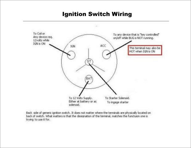
The ignition wiring diagrams show the different wires used for powering the different components. There are usually four colored terminus lines for each component. The accessories are colored red, the battery is yellow, and the starter solenoid green. The “IGN terminal allows you to start the car, control the wipers or other functions. The diagram shows the connection of the ACC- and ST terminals.
The terminal called BAT is the place where the battery is. The electrical system can’t be started without the battery. The switch will not turn off if the battery isn’t there. To find the battery in your car, check your wiring diagram. The accessory terminals of your car are connected to the ignition switch as well as the battery. The BAT Terminal is connected to the Battery.
Some ignition switches feature the “accessory” position that allows users to regulate their outputs without having to use the ignition. Sometimes, customers want to make use of an additional output that is independent of the ignition. You can utilize the auxiliary input by connecting it to the ACC terminal. Although this is a fantastic option, there’s a thing you need to know. Many ignition switches can be set to have an ACC location when the car has been moved into the ACC position. They also will be in START mode when the vehicle has entered the IGN position.
Gallery of Universal 4 Pole Ignition Switch Wiring Diagram
Gallery of Universal 4 Pole Ignition Switch Wiring Diagram


