Vw Golf Mk1 Ignition Switch Wiring Diagram – The first step is to take a look at the different kinds of terminals that are used on the ignition switch. These are the terminals used for Coil, Ignition Switch, and Accessory. Once we’ve determined the function of the terminals it is possible to recognize the various parts of the ignition wiring. We’ll also discuss the functions and the Coil. Then, we’ll turn our attention to Accessory terminals.
The ignition switch’s terminals
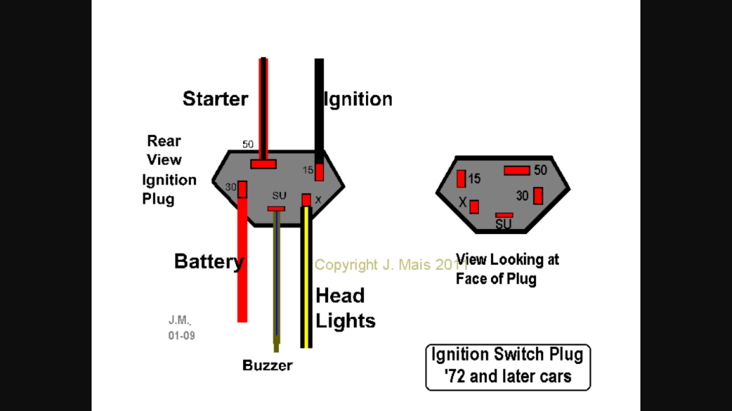
An ignition switch has three separate switches that feed the battery’s current to different destinations. The first switch powers the choke. The second switch controls the ON/OFF switch of the ignition switch. Different manufacturers use different color codes for various conductors. This is described in a different article. OMC uses this system. The ignition switch is also equipped with an adapter for the addition of a tachometer.
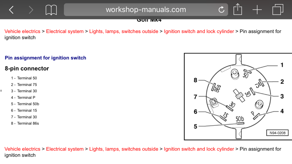
Although the majority of ignition switch terminals can be duplicated, the numbers might not be in line with the diagram. Before plugging into the ignition switch make sure to check the continuity. This can be done using an inexpensive multimeter. After you’re satisfied with the continuity of the wires connect the new connector. If your car is equipped with an original ignition switch supplied by the factory (or an electrical loom) the wiring loom might differ from that of the car.
In order to connect the ACC outputs to the auxiliary outputs on your car, you need to understand the way these two connections function. The ACC, IGN and START terminals are your default connection to the ignition switch. They also function as the primary connections to your radio and stereo. The ignition switch operates the engine’s switch to turn off or on. The terminals for the ignition switch on older cars are identified with the initials “ACC” as well as “ST” (for the individual magneto wires).
Terminals for coil
The terminology used to determine the model and type of the ignition coil is the most important thing. A simple diagram of the wiring will show a variety of terminals and connections including two primary and two secondary. You need to determine the type of coil you own by examining the voltage on the primary terminal S1. S1 must also be inspected for resistance to determine whether it’s a Type B, B, or A coil.
The chassis’ negative should be connected to connect the coil’s low-tension end. This is what you find in the wiring diagram. The high-tension supply provides the spark plugs with positive electricity directly. To reduce the noise the coil’s body metal must be connected with the chassis. It’s not necessary to use electricity. The wiring diagram for the ignition will explain how to connect the terminals of the positive and negative coils. Sometimes, a check at an auto parts store could identify a problem with the ignition wire.
The black-and-white-striped wire from the harness goes to the negative terminal. The terminal for the negative is served by the black trace connected to the white wire. The black wire is connected to the contact breaker. To verify the connection, employ a paperclip, or a pencil to remove them of the housing for the plug. Make sure the terminals aren’t bent.
Accessory Terminals
Ignition wiring diagrams show the different wires that are used to power the car’s various parts. There are generally four color-coded terminals that correspond to each component. Red is used for accessories and yellow is for the battery, and green is for the starter solenoid. The “IGN terminal lets you start the car, control the wipers or other functions. This diagram shows how to connect ACC and ST terminals to the rest of components.
The terminal BAT holds the battery. The electrical system can’t start without the battery. A dead battery can make the switch not come on. If you’re not sure of where your car’s battery is situated, examine your wiring diagram to figure out where it is. The ignition switch is connected to the battery of your car. The BAT terminal is connected to the battery.
Some ignition switches have an “accessory” setting that allows users to control their outputs without needing to utilize the ignition. Sometimes, users want to make use of an additional output that is not connected to the ignition. To make use of the additional output, wire the connector with the same colors as ignition and connect it to the ACC terminal on the switch. Although this is a fantastic option, there’s a thing you should know. Most ignition switches are set to have an ACC position when the vehicle is in the ACC position, while they’re set to the START position when the car is in the IGN position.
Gallery of Vw Golf Mk1 Ignition Switch Wiring Diagram
Gallery of Vw Golf Mk1 Ignition Switch Wiring Diagram


