Wiring Diagram For A Mercury Outboard Ignition Switch – Let’s start by looking at different types of terminals on the ignition switch. These are the terminals for the Ignition, Coil, or Accessory. Once we have identified the purpose of these terminals, we will determine the various components in the ignition wiring. In addition, we will discuss the different functions of the Ignition Switch and Coil. Then, we’ll turn our attention to Accessory terminals.
Terminals for ignition switches
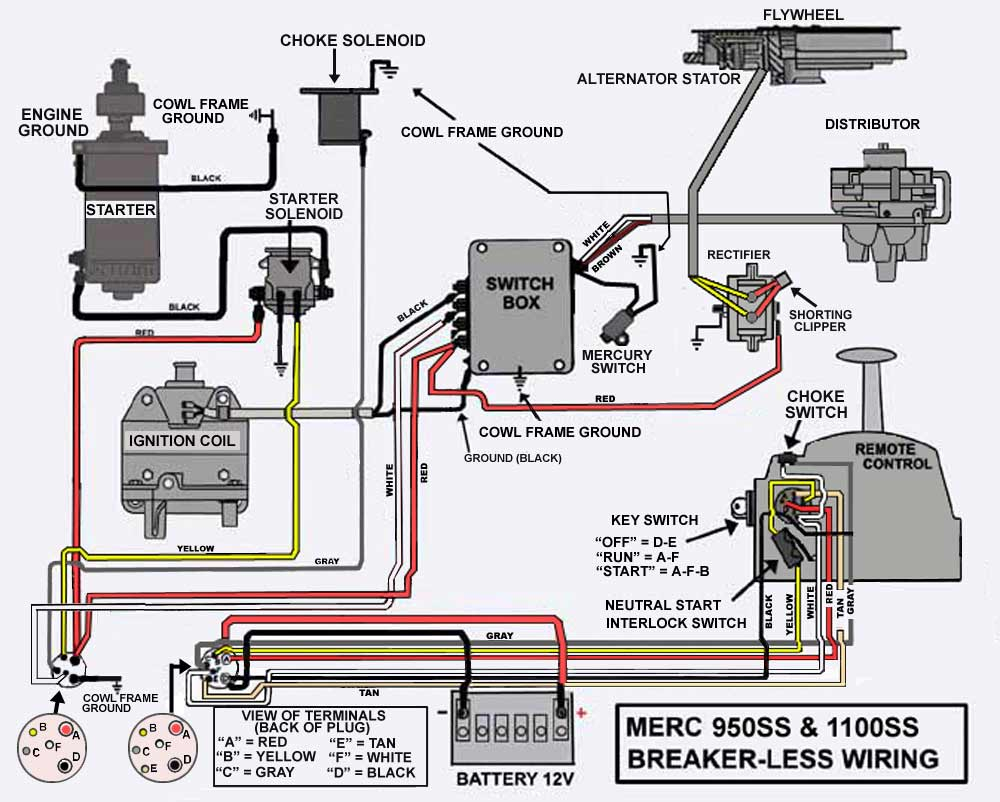
The ignition switch is comprised of three switches that supply the battery’s current to various locations. The first one is utilized to drive the choke by pushing it, and the second is for the ON/OFF position. Each manufacturer has their own color-coding system, which we will discuss in another article. OMC uses this method. A tachometer adapter is installed on the ignition switch to allow the addition of an tachometer.
Although the majority of ignition switch terminals do not come in original form, the numbering may not be in line with the diagram. To ensure that the wires are correctly plugged in to the ignition switch it is recommended to check their continuity. This can be accomplished using an inexpensive multimeter. When you’re satisfied with the continuity of your wires, you’ll be able to connect the new connector. The wiring loom for the ignition switch supplied by the factory will be different from the one that you have in your vehicle.
Understanding how ACC outputs connect to the other outputs of your car is vital. The ACC terminals as well as the IGN terminals function as the standard connections for the ignition switch. The START and IGN connections are the primary connections for stereo and radio. The ignition switch turns the car’s engine ON and OFF. Older cars are identified with the initials “ACC”, “ST”, (for individual magneto cables) at the ignition switch’s terminals.
Terminals for coil
The terms used to define the kind and model of an ignition coil is the primary thing. A simple diagram of the wiring will show a variety of terminals and connections comprising two primary and two secondaries. The voltage that operates on each coil is different. Therefore, it is important to first test the voltage at the S1 (primary terminal). S1 must also be subjected to resistance tests to determine if it are a Type A or B coil.
The negative end of the chassis must be connected to the coil’s low-tension side. This is also the ground in the ignition wiring diagram. The high-tension supply delivers positive directly to spark plugs. To reduce the noise, the coil’s metal body is required to be connected to the chassis. It is not required to connect electrically. The wiring diagram of the ignition will demonstrate how to connect the terminals of the positive or negative coils. It is possible to find an issue with the ignition coil that is easily identified by looking it up at an auto parts retailer.
The black-and-white-striped wire from the harness goes to the negative terminal. The other white wire is black and connects to the negative terminal. The black wire is connected to the contactbreaker. To verify the connections between the two wires, use a paperclip and lift them from the housing. It is also important to ensure that the terminals don’t bend.
Accessory Terminals
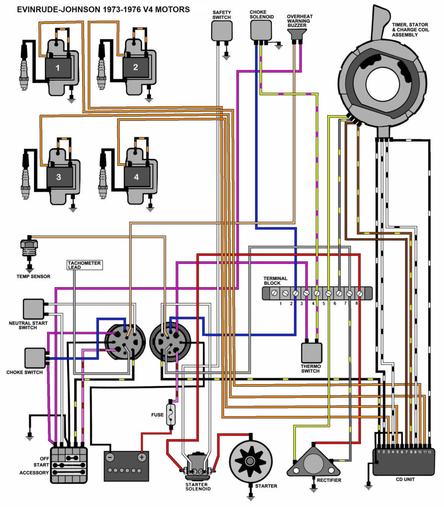
Ignition wiring diagrams depict the various wires that are used to power various components. Typically, there are four different colors-coded terminals that are used for each component. Red stands for accessories, yellow represents the battery and green is for the solenoid for starters. The “IGN” terminal allows you to start the car, manage the wipers, and any other features that operate. The diagram illustrates the connection to the ACCand ST terminals.
The battery is connected to the terminal whose name is BAT. The electrical system won’t start when the battery isn’t connected. The switch also won’t turn on without the battery. To find the battery in your car look over your wiring diagram. The accessory terminals of your car are connected to the ignition switch as well as the battery. The BAT terminal is connected to the battery.
Certain ignition switches come with an additional position in which users can adjust their outputs as well as control them without the need to use the ignition. Some customers prefer to use an auxiliary output independent of the ignition. To use the additional output, wire the connector using identical colors to the ignition connecting it to the ACC terminal on the switch. This feature is convenient, but it has one key differentiator. Most ignition switches come with the ACC position when your car is in ACC mode, and a START position when it is in IGN.
Gallery of Wiring Diagram For A Mercury Outboard Ignition Switch
Gallery of Wiring Diagram For A Mercury Outboard Ignition Switch


