Wiring Diagram For Ignition Coil With Points – We will first examine the various types of terminals found on the ignition switch. The terminals are the Ignition switch as well as the Coil along with the Accessory. Once we have identified what these terminals are then we can be able to identify the various parts of the ignition wiring. In addition, we will discuss the functions of both the Ignition Switch and Coil. Following that, we’ll shift our attention to the Accessory terminals.
Terminals for ignition switches
An ignition switch is made up of three different switches. They are the ones that supply the battery’s power to various destinations. The choke is powered by the first switch. The second switch is responsible for the ON/OFF function of the ignition switch. Different manufacturers have distinct colors-coding systems to match the conductors. OMC uses this method. A tachometer adapter is installed on the ignition switch that allows the addition of a tachometer.
Even though some ignition switch terminals do not come in original form, the numbering may not match the diagram. To ensure that your wires are properly connected to the switch, you should check their continuity. A simple multimeter will help you do this. When you’re satisfied with the integrity of your wires, you will be able to connect the new connector. If your vehicle is equipped with an ignition switch installed the wiring diagram will differ.
Knowing how the ACC outputs are connected to the other outputs inside your car is essential. The ACC and IGN connectors are the default connections of your ignition switch. While the START, IGN, and ACC terminals are the main connections to the radio or stereo, the START/IGN connections are the main ones. The ignition switch turns the car’s engine on and OFF. Older cars have the ignition switch terminals marked “ACC” or “ST” (for individual magnetowires).
Terminals for Coil
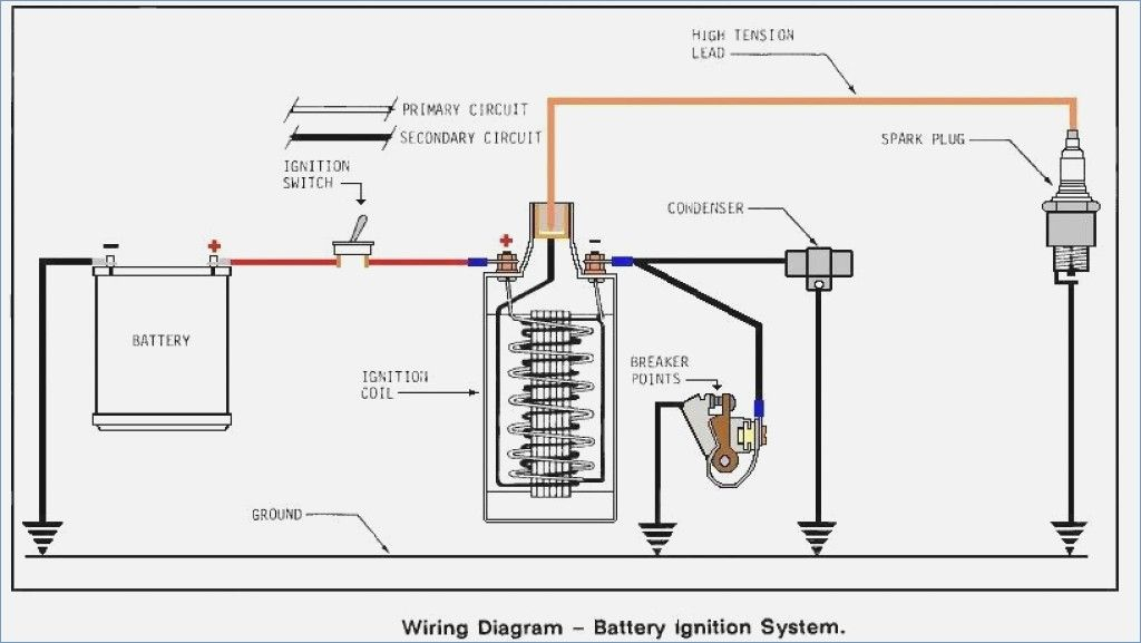
Understanding the terminology is the initial step towards knowing what type of ignition coil you’ve got. A simple diagram of the wiring will display a range of terminals and connections which include two primary terminals and two secondaries. The operating voltage of each coil is different. Therefore, it is important to first test the voltage at the S1 (primary terminal). Also, you should examine S1 for resistance to identify if it’s a Type A or B coil.
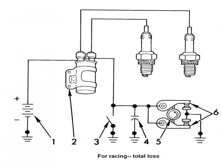
The coil’s low-tension side must be connected with the chassis positive. This is the base of the wiring for ignition. The high tension part supplies positive power directly to the spark plugs. It is necessary for the purpose of suppression that the metallic body of the coil is connected to its chassis, but not essential. The wiring diagram will show the connection between the positive and negative coil terminals. Sometimes, a visit to an auto parts shop can diagnose a malfunctioning ignition wire.
The black-and-white-striped wire from the harness goes to the negative terminal. The other white wire is black-colored and connects to the negative terminal. The black wire connects to the contact breaker. If you’re not sure about the connections of both, you can use the clip of a paperclip to remove them from the housing of the plug. Make sure you verify that the connections have not been bent.
Accessory terminals
Diagrams of ignition wiring show the different wires used for powering the various components. There are usually four colored terminus lines for each component. For accessories, red is for starter solenoid, yellow for battery and blue for accessories. The “IGN terminal is used for starting the car, controlling the wipers and various other functions. The below diagram shows how to connect the ACC terminal as well as the ST terminals to the other components.
The terminal BAT is where the battery is. The electrical system cannot start without the battery. In addition, the switch will not begin to turn on. It is possible to refer to your wiring diagram if you are uncertain about where the car’s batteries are. The ignition switch is linked to the car’s battery. The BAT terminal is connected with the battery.
Some ignition switches come with an additional “accessory position” that lets users alter their outputs without the ignition. Sometimes, customers want to utilize an additional output independent of the ignition. To use the additional output, wire the connector using the same colors as the ignition and connect it to the ACC terminal on the switch. While this is an excellent feature, there is one important difference. Some ignition switches are configured to be in an ACC position once the car has been moved into the ACC position. They also will be in START mode after the vehicle has been moved into the IGN position.
Gallery of Wiring Diagram For Ignition Coil With Points
Gallery of Wiring Diagram For Ignition Coil With Points


