Wiring Diagram Ignition Coil – First, let’s examine the various terminals on the ignition switch. They include terminals for the Ignition switch, Coil, and Accessory. Once we’ve determined the function of the terminals we can identify the various parts of the ignition wiring. We’ll also discuss the roles of both the Ignition Switch and Coil. After that we will proceed to the Accessory Terminals.
Terminals for ignition switch
An ignition switch has three switches that supply the battery’s current to various locations. The first switch powers the choke. The second switch controls the ON/OFF of the ignition switch. Different manufacturers employ different colors for various conductors. This is explained in a separate article. OMC uses this system. A tachometer adapter is installed on the ignition switch to allow the addition of a Tachometer.
Even though most ignition switch terminals don’t carry an original number, they might have a different one. Check the electrical continuity first to ensure they’re connected correctly to the ignition switch. A multimeter that is inexpensive can help you do this. Once you are satisfied with the continuity of the wires you can install the new connector. If you have an ignition switch that is supplied by the manufacturer, the wiring loom is different from the one you have in your car.
In order to connect the ACC outputs to the auxiliary outputs on your vehicle, you have to understand how these two connections work. The ACC, IGN and START terminals are the primary connections to the ignition switch. They are also the primary connections to your radio and stereo. The ignition switch switches the car’s engine on and off. On older cars, the ignition switch terminals are marked with the initials “ACC” and “ST” (for the individual magnetic wires).
Terminals for coil
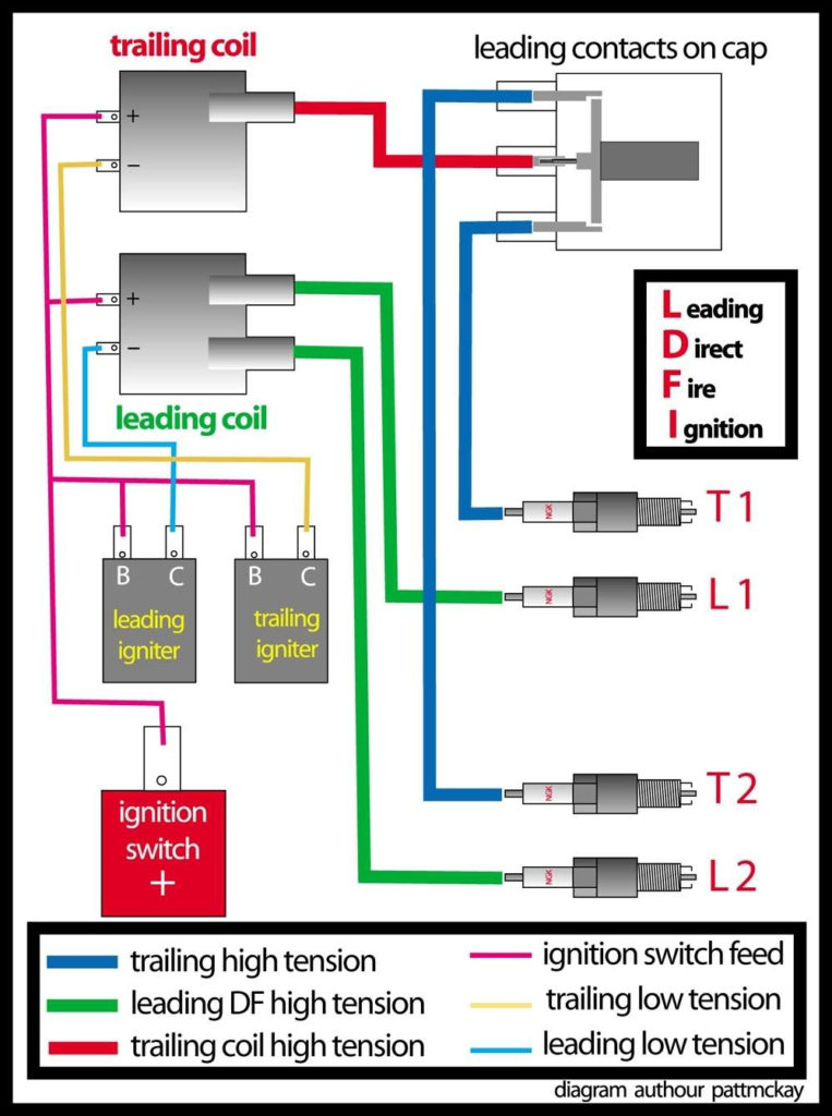
Understanding the terms is the initial step in knowing what type of ignition coil you have. You’ll see a number of connections and terminals within the basic wiring diagram for ignition that include two primary and two secondary. Each coil has a specific operating voltage. To determine the type of coil you have, the first step is to test the voltage at the S1 primary terminal. S1 should also be tested for resistance to determine whether it’s a Type B, B, or an A coil.
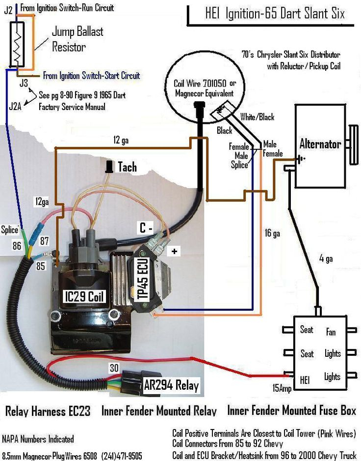
The coil’s low-tension side must be connected with the chassis positively. This is the base of the ignition wiring. The high-tension part provides the spark plugs with positive. For suppression purposes the coil’s metal body must be connected with the chassis. It is not required to use electricity. The wiring diagram for the ignition will explain how to connect the terminals of the positive or negative coils. Sometimes, a visit to an auto part store can diagnose a malfunctioning ignition wire.
The black-and-white-striped wire from the harness goes to the negative terminal. The other white wire has a black color and goes to the negative terminal. The black wire is connected to the contactbreaker. To verify the connections between the two wires use a paperclip to lift them out of the housing. Make sure that the connectors do not bend.
Accessory terminals
The wiring diagrams of the ignition illustrate the various wires that power the various components of the vehicle. Each component has four distinct connections that are color coded. For accessories, red is the starter solenoid’s color, blue for battery and blue for accessories. The “IGN terminal allows you to start the car, control the wipers, and any other operation features. The diagram illustrates how to connect ACC or ST terminals and the rest.
The terminal BAT connects the battery to the charger. Without the battery the electrical system can not get started. Additionally, the switch will not be able to turn on without the battery. If you don’t know where your car’s battery is located, you can examine your wiring diagram to see the best way to find it. Your car’s accessory terminals are connected to the ignition switch as well as the battery. The BAT terminal is connected to the battery.
Some ignition switches feature an “accessory” position that permits users to control their outputs , without needing to utilize the ignition. Sometimes, customers want to make use of an additional output that is independent of the ignition. To make use of the auxiliary output, connect the connector using the same colors as the ignition connecting it to the ACC terminal on the switch. Although this is a great feature, there’s something you should know. The majority of ignition switches are set to operate in the ACC position when the car is in the ACC position, while they’re in the START position when the car is in the IGN position.
Gallery of Wiring Diagram Ignition Coil
Gallery of Wiring Diagram Ignition Coil


