Wiring Harness Toyota Ignition Switch Wiring Diagram – The first step is to look at the different terminals on the ignition switch. These are the terminals that connect the Ignition, Coil, or Accessory. Once we know which terminals are used, we can begin to identify the different components of the Wiring Harness Toyota Ignition Switch Wiring Diagram. We will also cover the different functions of the Ignition Switch and Coil. Then, we’ll talk about the functions of the Ignition switch and Coil.
Terminals of ignition switch
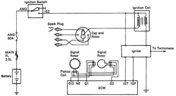
An ignition switch is composed of three switches. They are responsible for supplying the battery’s power to various destinations. The first switch is the one that supplies the choke with power, while the second switch controls the on/off status of the ignition switch. Every manufacturer has its unique color-coding system, which we’ll go over in a separate article. OMC follows this method. There is a connector in the ignition switch for connecting an Tachometer.
Although the majority of ignition switch terminals don’t carry an original number, they may be equipped with a different number. Check the electrical continuity to see if they are connected to the ignition switch correctly. A multimeter is a good tool to check the continuity. When you are satisfied with the continuity of the wires, it is time to install the new connector. The wiring loom used in a factory-supplied ignition system switch is different.
First, understand the differences between ACC and secondary outputs. The ACC terminals as well as the IGN terminals serve as the default connections to the ignition switch. The START and IGN connections are the most important connections for stereo and radio. The ignition switch is the one that controls the engine of your car. Older vehicles have ignition switch terminals marked “ACC” or “ST” (for individual magnetowires).
Terminals for coil
The first step in determining the kind of ignition coil is to understand the terminology used. There are a variety of connections and terminals on a basic ignition wiring schematic which includes two primary as well as two secondary. Each coil is equipped with a distinct operating voltage. To determine the type of coil you own the first step is to determine the voltage at the S1 primary terminal. S1 must also go through resistance tests to determine if it are an A or B coil.
The coil’s low-tension component is to be connected to the chassis positive. It is also the ground in the diagram of ignition wiring. The high-tension supply provides positive directly to spark plugs. The metal body of the coil needs to connect to the chassis to suppress the effect however it isn’t electrically necessary. You will also see the connections of the negative and positive coil’s terminals on an ignition wiring diagram. In some instances it is possible to find an ignition coil that is malfunctioning is identified by scanning in an auto parts store.
The black-and-white-striped wire from the harness goes to the negative terminal. The positive terminal also receives the white wire that includes a black trace. The black wire is connected to the contact breaker. If you’re unsure of the connection between the twowires, use the clip of a paperclip to remove them from the plug housing. Make sure that the terminals do not bend.
Accessory terminals

Ignition wiring diagrams depict the various wires utilized to power the different components. There are usually four different colors of terminals connected to each part. The red symbol represents accessories, yellow is for the battery and green is for the solenoid for starters. The “IGN” terminal is used for starting the vehicle, controlling the wipers and various other functions. The diagram illustrates the connection of the ACC- and ST terminals.
The battery is connected to the terminal named BAT. The electrical system can’t be started without the battery. The switch also won’t turn on without the battery. If you’re not sure of where your car’s battery is situated, you can review the wiring diagram of your car to determine how to locate it. The ignition switch and the battery are connected through the accessory terminals. The BAT terminal is connected to the battery.
Some ignition switches have the “accessory” position that permits users to control their outputs without having to use the ignition. Sometimes, users want to utilize an additional output that is not connected to the ignition. Make use of the auxiliary output by connecting it to an ACC terminal on your switch that has the same color. This is a convenient feature, but it has one major difference. Most ignition switches will be in an ACC position if the car is in the ACC, but they will be in the START position if the car is in IGN.
Gallery of Wiring Harness Toyota Ignition Switch Wiring Diagram

Gallery of Wiring Harness Toyota Ignition Switch Wiring Diagram


