Yamaha Moto 4 Ignition Switch Wiring Diagram – In the beginning, we’ll look at the different types of terminals that are found on the ignition switch. These include the terminals for the Ignition switch, Coil, and Accessory. Once we know which terminals are used then we can recognize the various parts of the Yamaha Moto 4 Ignition Switch Wiring Diagram. In addition, we will discuss the different functions of the Ignition Switch and Coil. Following that, we’ll shift our attention to Accessory terminals.
Terminals for ignition switches
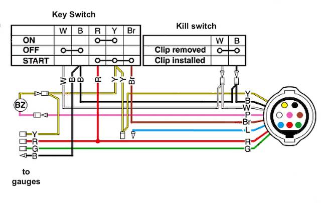
An ignition switch is composed of three different switches. These are responsible for supplying the battery’s energy to various locations. The first one is used to power the choke through pushing it, and the third switch is used to control the ON/OFF position. Different manufacturers have different color-coding schemes to identify different conductors. We’ll discuss this in a different article. OMC utilizes the same system. A tachometer adapter is installed on the ignition switch to allow for the addition of a tonometer.
While the majority of ignition switch terminals don’t have an original number, they may have a different one. To ensure that your wires are correctly connected to the switch, you should check their continuity. A multimeter is a good tool to test the continuity. Once you’re satisfied about the continuity of your wires, you’ll be able to connect the new connector. If your car is equipped with an original ignition switch supplied by the factory (or an electrical loom), the wiring loom will differ from that in your car.
First, understand the differences between the ACC and the auxiliary outputs. The ACC, IGN and START terminals are the primary connections to the ignition switch. They also function as the main connections to the radio and stereo. The ignition switch is responsible to turn the car’s engines on and off. Older cars are equipped with ignition switch terminals marked “ACC” or “ST” (for individual magnetowires).
Terminals for coil
The terms used to define the type and model of the ignition coil is the most important thing. You will see several connections and terminals on the basic wiring diagram for ignition, including two primary, and two secondary. The voltage that operates on each coil is different. This is why it is important to first test the voltage at S1 (primary terminal). It is also recommended to test S1 for resistance to identify if it’s a Type A B, C, or coil.
The chassis’ negative end should be connected to connect to the coil’s lower-tension end. This is also the ground in the diagram of ignition wiring. The high tension part supplies positive power directly to the spark plugs. It is essential for the purpose of suppression that the body of the coil’s metal be connected to its chassis but not essential. The wiring diagram of the ignition will explain how to connect the terminals of the negative or positive coils. In certain instances, you’ll find that a malfunctioned ignition coil can be diagnosed with a scan at an auto parts store.
The black-and-white-striped wire from the harness goes to the negative terminal. The other white wire is black and connects to the negative terminal. The black wire connects with the contact breaker. If you’re not certain about the connections of the two, try using a paper clip to remove them from the housing of the plug. Be sure to ensure that the terminals haven’t been bent.
Accessory Terminals
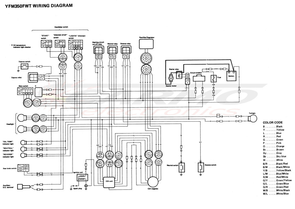
Diagrams of ignition wiring show the various wires that are used to power the different components. Typically there are four color-coded terminals for each component. The red color represents accessories, yellow for the battery, and green for the solenoid for starters. The “IGN” terminal is used to start the car, operating the wipers, and for other functions. The diagram illustrates how to connect ACC or ST terminals, and other.
The battery is attached to the terminal named BAT. Without the battery, the electrical system does not start. The switch also won’t be able to turn on without the battery. You can refer to your wiring diagram if uncertain about where the car’s batteries are. The accessory terminals of your car connect to the battery as well as the ignition switch. The BAT Terminal is connected to the Battery.
Certain ignition switches have an additional “accessory” location, which allows users can control their outputs without the ignition. Sometimes, customers wish to utilize the auxiliary output separate from the ignition. For the auxiliary output to be used, wire the connector in the same shade as the ignition. Then connect it with the ACC end of the switch. This is a great feature, however there’s an important distinction. A majority of ignition switches feature an ACC position when the car is in the ACC mode and a START mode when the switch is in IGN.
Gallery of Yamaha Moto 4 Ignition Switch Wiring Diagram
Gallery of Yamaha Moto 4 Ignition Switch Wiring Diagram


