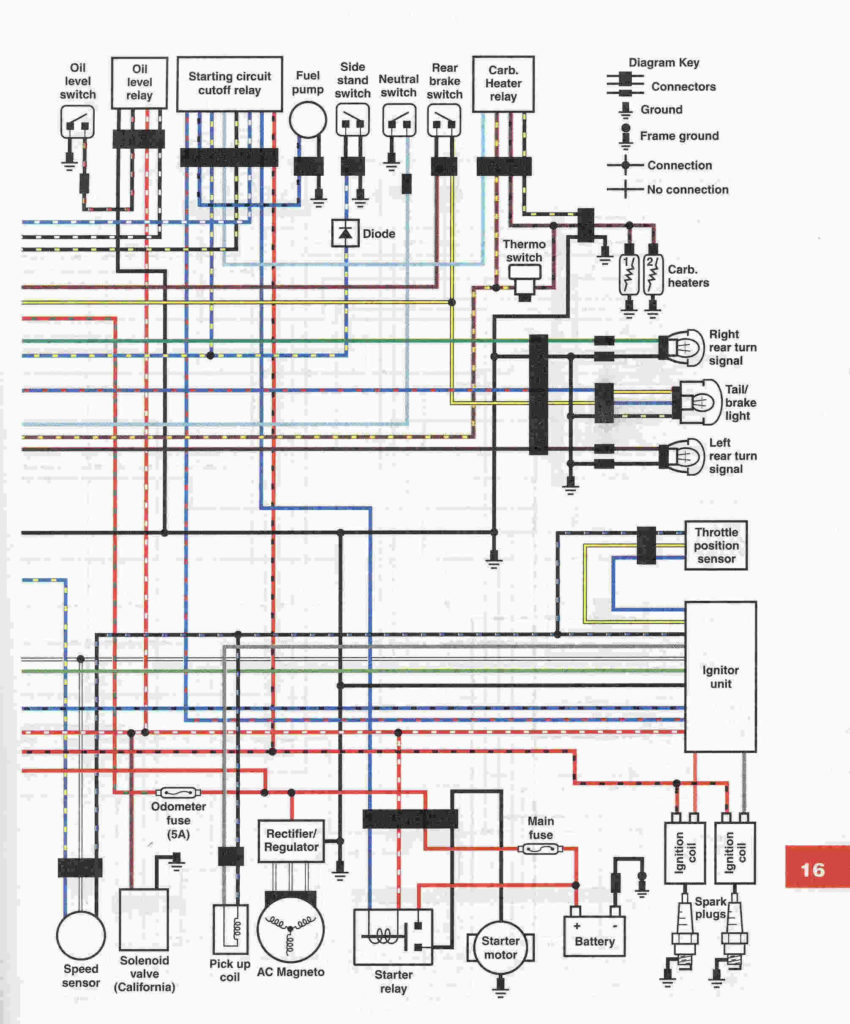
Yamaha R6 Ignition Wiring Diagram – Let’s first take a look at the different types of terminals that are used in the ignition switch. These terminals are used for the Ignition button, Coil and Accessory. Once we understand the function of each terminal, it is possible to identify the parts of the ignition wiring. In addition, we will discuss the roles of the Ignition switch and Coil. Then, we will turn our attention towards the accessories terminals.
Terminals for the ignition switch
Three switches are located on an ignition switch. Each of these switches is able to feed the battery’s voltage to a variety of locations. The ON/OFF position of the ignition switch is controlled by the second switch, which delivers power to the choke whenever it is pushed. Different manufacturers use different colors for different conductors. This is described in a separate article. OMC employs this system. The ignition switch comes with an adapter for the addition of a tachometer.
Although the majority of ignition switch terminals are not original, the numbers for each might not be consistent with the diagram. Before you plug into the ignition switch, ensure that you check the continuity. This can be checked with a simple multimeter. When you are satisfied with the integrity of the wires, install the new connector. The wiring loom of the ignition system switch supplied by the manufacturer differs.
For connecting the ACC outputs to the auxiliary outputs on your car, you’ll need to first understand the way these two connections function. The ACC, IGN and START terminals are your default connections to the ignition switch. They are also the primary connections to the radio and stereo. The ignition switch is accountable to turn the car’s engines on and off. The terminals for the ignition switch on older vehicles are marked with the letters “ACC” and “ST” (for the individual magneto wires).
Terminals for coil
To figure out the type of ignition coil, the first step is to know the terms. The diagram of the basic ignition wiring illustrates a variety of connections and terminals. There are two primary and secondary connections. The operating voltage of every coil is different. Therefore, it is essential to first check the voltage at the S1 (primary terminal). S1 should also undergo resistance testing to determine whether it is an A or B coil.
The coil’s low-tension side must be connected to the chassis positive. This is also the ground for the diagram of ignition wiring. The high-tension supply supplies positively directly to spark plugs. To reduce the noise, the coil’s body metal must be connected with the chassis. It is not required to use electricity. The wiring diagram for the ignition will demonstrate how to connect the terminals of either the positive or negative coils. Sometimes, a damaged ignition coil can be detected through a scan performed at an auto repair shop.
The black-and-white-striped wire from the harness goes to the negative terminal. The white wire is black-colored and goes to the negative terminal. The black wire is connected to the contact breaker. To check the connections, make use of a paperclip or pencil to lift them out of the housing for the plug. It’s also crucial to make sure the terminals aren’t bent.
Accessory terminals
The wiring diagrams for the ignition show the various wires that are used to power various components of the vehicle. There are usually four colored terminals that correspond to the component. The red color is used for accessories and yellow is for the battery, while green is for the solenoid for starters. The “IGN” terminal lets you start your car, operate the wipers or other functions. The below diagram illustrates how to connect the ACC terminal and ST terminals to the other components.
The terminal BAT is the connector for the battery. The electrical system will not start without the battery. The switch won’t turn off if the battery isn’t present. It is possible to view your wiring diagram to determine where the batteries of your car are located. The ignition switch and battery are connected by the accessory terminals. The BAT terminal is connected to the battery.
Some ignition switches have the “accessory” position that permits users to control their outputs , without needing to turn on the ignition. Customers may want to utilize the auxiliary output independently of the ignition. You can use the secondary input by connecting it to the ACC terminal. Although this is a great feature, there’s one thing you should know. Most ignition switches will be in an ACC position if the car is in ACC however they will be at the START position if the vehicle is IGN.
Gallery of Yamaha R6 Ignition Wiring Diagram
Gallery of Yamaha R6 Ignition Wiring Diagram


