Yamaha V Star 1100 Ignition Switch Wiring Diagram – We will first look at the various kinds and functions of terminals found in the ignition switches. They include terminals for the Ignition switch, Coil, and Accessory. Once we have identified which terminals are used and which ones are not, we can identify the different components of the Yamaha V Star 1100 Ignition Switch Wiring Diagram. We will also discuss what functions are available for the Ignition switch, as well as the Coil. Then, we will turn our attention towards the accessory terminals.
The terminals are for ignition switches.
Three switches can be found on an ignition switch. Each of the three switches feeds the battery’s voltage to various locations. The first switch supplies power to the choke whenever it is pushed. The second is the ignition switch’s ON/OFF position. Every manufacturer has its individual color-coding system that we’ll go over in a separate article. OMC utilizes the same system. The ignition switch also includes an adapter for the addition of a timer.
Although most ignition switch terminals are duplicated, the numbers might not be in line with the diagram. Check the integrity of the wires first to ensure that they are correctly plugged in the ignition switch. A multimeter is a good tool to test the continuity. When you are satisfied with the integrity of the wires, install the new connector. If your car is equipped with an original factory-supplied ignition switch (or a wiring loom) the wiring loom might differ from that of your car.
Before you can connect the ACC outputs to your car’s auxiliary outputs It is essential to be familiar with the fundamentals of these connections. The ACC terminals as well as the IGN terminals are the primary connections to the ignition switch. The START and IGN connections are the primary connections for stereo and radio. The ignition switch acts as the engine’s on/off button. The ignition switch terminals on older cars are identified with the letters “ACC” as well as “ST” (for the individual magneto wires).
Terminals for coil
Understanding the terms that is used is the first step to determining the kind of ignition coil to choose. You will see several connections and terminals within an ignition wiring schematic which includes two primary as well as two secondary. The operating voltage of each coil differs. This is why it is essential to first check the voltage at the S1 (primary terminal). S1 should also be checked for resistance in order to identify if the coil is a Type B, B or an A coil.
The negative end of the chassis should be connected to the coil’s low-tension side. This is the ground on the diagram of ignition wiring. The high-tension supply delivers positively directly to spark plugs. The aluminum body of the coil has to be connected to the chassis to prevent it from being smothered but isn’t required. The wiring diagram for the ignition will show you how to connect the terminals of either the negative or positive coils. Sometimes, a check at an auto parts shop can diagnose a malfunctioning ignition wire.
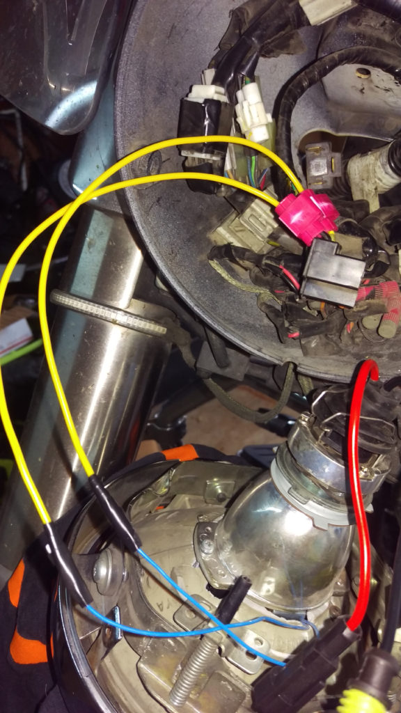
The black-and-white-striped wire from the harness goes to the negative terminal. The other white wire is black with a trace on it and it goes to the positive terminal. The contact breaker is linked to the black wire. To confirm the connections, use a paperclip or a pencil to lift them out from the plug housing. You should also check to ensure that the terminals are not bent.
Accessory terminals
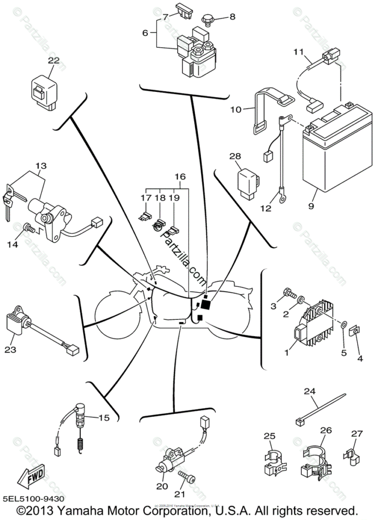
The ignition wiring diagrams illustrate the various wires that power the various components of the vehicle. Each component is equipped with four distinct connections that are color coded. The accessories are red while the battery is yellow the starter solenoid green. The “IGN terminal is used for starting the car, controlling the wipers, and for other functions. The diagram illustrates the connection to the ACC- and ST terminals.
The battery is connected to the terminal whose name is BAT. The electrical system won’t start without the battery. The switch also won’t turn on without the battery. A wiring diagram can inform you the location of the battery of your car. The ignition switch is linked to the car’s battery. The BAT terminal is connected to the battery.
Certain ignition switches have a separate “accessory” position, where users can control their outputs without the ignition. Sometimes, customers may wish to utilize the auxiliary output separately from the ignition. For the auxiliary output to be used, plug in the connector in the same shade as the ignition. Connect it to the ACC end of the switch. Although this is a useful feature, there’s one important difference. The majority of ignition switches are configured to have an ACC status when the car’s at the ACC or START positions.
Gallery of Yamaha V Star 1100 Ignition Switch Wiring Diagram
Gallery of Yamaha V Star 1100 Ignition Switch Wiring Diagram


