Yamaha Zuma Ignition Wiring Diagram – Let’s begin by looking at the various types terminals found on an ignition switch. The terminals are the Ignition switch and Coil and the Accessory. Once we know the purpose of each kind of terminal, we can then determine the components of the ignition wiring. We will also cover the functions of both the Ignition Switch and Coil. After that, we will focus on the accessory terminals.
Terminals of ignition switch
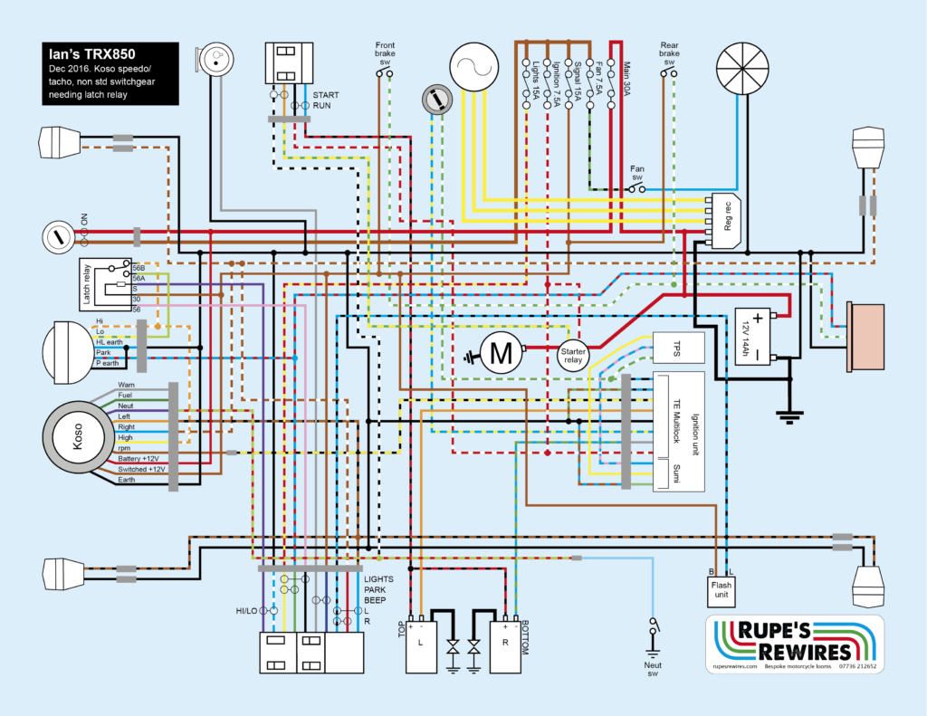
An ignition switch is comprised of three switches. They transmit the battery’s voltage to many different places. The first one is utilized to power the choke through pushing it, and the second is for the ON/OFF setting. Different manufacturers utilize their own color-coding method for the various conductors, which is documented in another article. OMC uses this method. The adapter is attached to the ignition switch, allowing the addition of an tonometer.
Although most ignition switch terminals are duplicated, the numbers might not match the diagram. Check the electrical continuity first to make sure they’re properly connected to the ignition switch. A multimeter is a good tool to test the continuity. Once you are happy with the continuity of the wires, you can connect the new connector. The wiring loom in a factory-supplied ignition system switch is different.
In order to connect the ACC outputs to the auxiliary outputs of your car, you’ll need to first understand the way these two connections function. The ACC/IGN connections function as the default connection on the ignition switch. The START/IGN terminals are connected to the stereo or radio. The ignition switch is the one that controls the engine of your car. The ignition switch terminals on older cars are identified with the initials “ACC” as well as “ST” (for the individual magneto wires).
Terminals for Coil
To figure out the type of ignition coil you need to know the step is to know the terms. In a basic diagram of the wiring for ignition you’ll see various terminals and connections, including two primary and two secondary. Each coil is operating at a certain voltage. The first step to determine which kind of coil you’re using is to examine the voltage on S1, or the primary terminal. S1 should also undergo resistance testing to determine whether it’s a Type A or B coil.
The chassis’ negative needs to be connected to the side of low-tension. This is what’s called the ground in the diagram of the ignition wiring. The high tension part supplies positively directly to the spark plugs. It is necessary for the purpose of suppression that the body of the coil’s metal be connected to its chassis, however, it is not necessary. The diagram of the ignition wiring will also indicate the connection of the positive coil terminals. In some cases scanning your local auto parts store will help identify defective ignition coils.
The black-and-white-striped wire from the harness goes to the negative terminal. The white wire is the other one. It is black with a trace on it, and it goes to the positive terminal. The black wire connects to the contact breaker. You can take the black wire from the plug housing by using a paperclip if you are unsure about the connections. Make sure you verify that the connections haven’t been bent.
Accessory terminals
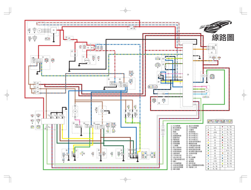
The ignition wiring diagrams illustrate the various wires utilized to power the vehicle’s various parts. There are generally four colored terminals that correspond to the respective component. The accessories are colored red, the battery is yellow the starter solenoid green. The “IGN” terminal can be utilized to turn on the car, operate the wipers and other functions. The diagram shows how to connect ACC or ST terminals as well as the rest.
The terminal BAT is the connection to the battery. The battery is necessary for the electrical system to start. Additionally, the switch will not be able to turn on without the battery. If you’re not sure of the exact location where the battery in your car is situated, review the wiring diagram of your car to determine the best way to find it. The accessory terminals of your vehicle are connected to the battery as well as the ignition switch. The BAT terminal connects to the battery.
Some ignition switches come with a separate “accessory” position, in which users can control their outputs without using the ignition. In some cases, users may want to use the auxiliary output separately from the ignition. You can use the additional output by connecting the connector to an ACC terminal on your switch that has the same color. While this is an excellent option, there’s a thing to be aware of. Most ignition switches are designed to display an ACC status when the car is at the ACC or START position.
Gallery of Yamaha Zuma Ignition Wiring Diagram
Gallery of Yamaha Zuma Ignition Wiring Diagram


