04 Sentra Ignition Switch Wiring Diagram – Let’s first examine the different types and functions of the terminals found in the ignition switches. These are the terminals that connect the Ignition, Coil, or Accessory. After we’ve established the purpose of these terminals are We will then identify the different parts of the 04 Sentra Ignition Switch Wiring Diagram. We’ll also go over the function of the Ignition switch and Coil. After that we will discuss the Accessory Terminals.
Terminals for the ignition switch
The ignition switch has three switches. They supply the battery’s voltage to many different places. The first one supplies the choke with power when it is pushed. The third is the switch that controls the ignition’s ON/OFF positions. Different manufacturers have their own color-coding system for different conductors which is explained in a different article. OMC utilizes this method. The adapter is attached to the ignition switch to allow the installation of an tonometer.
Even though most ignition switch terminals don’t carry an original number, they might have a different one. Before you plug in the ignition switch, be sure to test the continuity. A multimeter is an excellent instrument to verify the continuity. After you have verified the integrity of the wires you are able to install the connector. The wiring loom of a factory-supplied ignition system switch is distinct.
You must first understand how the ACC outputs and the auxiliary outputs function to join them. The ACC, IGN and START terminals are your default connection to the ignition switch. They also serve as the primary connections to your radio and stereo. The ignition switch is responsible for turning the car’s engine on and off. The terminals of older vehicles ignition switches are identified by “ACC” as well as ST (for the individual magneto wires).
Terminals for coil
The terminology used to determine the model and type of an ignition coil is the primary thing. The basic ignition wiring diagram depicts various connections and terminals. There are two primary and one secondary. Each coil is equipped with a distinct operating voltage. To determine which type of coil you own, the first step is to test the voltage at the S1 primary terminal. S1 must also be subjected to resistance testing to determine whether it is an A or B coil.
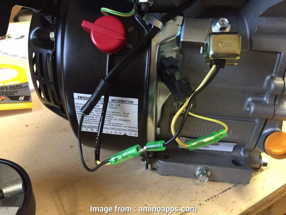
The low-tension side of the coil must be connected to the chassis’ negative. This is also the ground on the ignition wiring diagram. The high-tension supply delivers positively directly to spark plugs. To reduce the noise, the coil’s metal body must be connected to the chassis. But, it’s not necessary to connect the coil electrically. The diagram of the ignition wiring will also show you how to connect the positive and negative coil terminals. It is possible to find an issue with the ignition coil which can be identified by scanning it at an auto parts retailer.
The black-and-white-striped wire from the harness goes to the negative terminal. The terminal for the negative is served by the black trace attached to the white wire. The black wire connects to the contact breaker. You can examine the connections using a paperclip to take the wires out from the housing. Be sure to verify that the connections haven’t been bent.
Accessory terminals
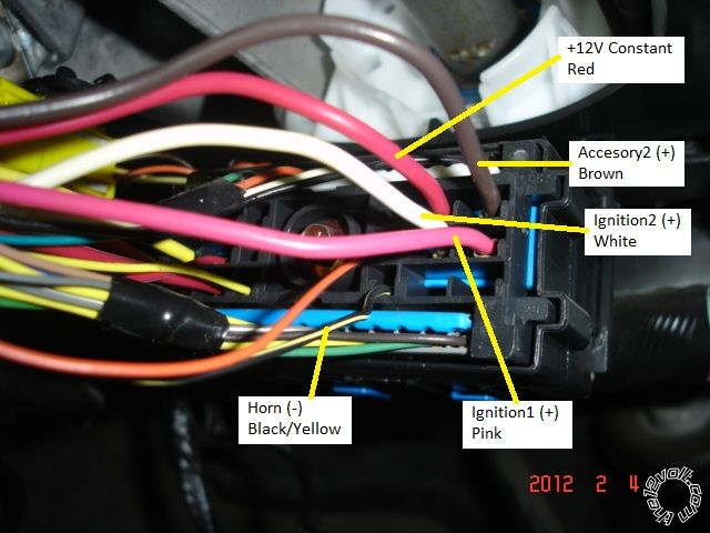
Diagrams of the ignition wiring illustrate the wires used to power various parts of the vehicle. There are generally four colors of terminals connected to each part. Red is for accessories while yellow is the battery, while green is for the starter solenoid. The “IGN” terminal is utilized to turn on the car, operate the wipers, as well as other features. The diagram shows how you can connect the ACC and ST terminals to the rest of the components.
The battery is connected to the terminal named BAT. The battery is vital to allow the electrical system to start. The switch also won’t start without the battery. If you’re not sure where your car’s battery is situated, review the wiring diagram of your car to determine where it is. The accessory terminals in your vehicle connect to the battery as well as the ignition switch. The BAT Terminal is connected to the battery.
Certain ignition switches come with an additional position in which users can alter their outputs and manage them without needing to use the ignition. Some customers might want to utilize the auxiliary input separately from the ignition. The auxiliary output is utilized by wiring the connector in the same color as your ignition, and then attaching it to the ACC terminal of the switch. This feature of convenience is fantastic however there’s a difference. A lot of ignition switches can be set to have an ACC position once the car is in the ACC position. They’ll also be in the START mode once the vehicle is entered the IGN position.
Gallery of 04 Sentra Ignition Switch Wiring Diagram
Gallery of 04 Sentra Ignition Switch Wiring Diagram


