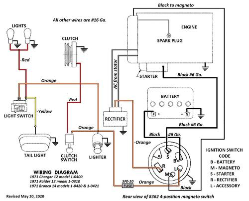
1979 Bronco Ignition Wiring Diagram – First, we will examine the different types of terminals for the ignition switch. These terminals include the Ignition switch and Coil along with the Accessory. After we’ve identified the purpose of the terminals it is possible to determine the various components of the ignition wiring. We’ll also go over the function of the Ignition switch and Coil. After that we will proceed to the Accessory Terminals.
The terminals are for ignition switches.
An ignition switch has three switches. They transmit the voltage of the battery to different locations. The first is utilized to drive the choke through pushing it. Then, the second is for the ON/OFF setting. Each manufacturer has its unique color-coding system, which we will discuss in another article. OMC uses the same method. A connector is also included inside the ignition switch to allow connecting the tachometer.
Although the majority of ignition switch terminals can be duplicated, the number may not match the diagram. Before plugging into the ignition switch make sure to check the continuity. You can do this with a simple multimeter. Once you’re satisfied about the integrity of your wires, you will be able install the new connector. The wiring loom used in a factory-supplied ignition system switch differs.
Understanding how the ACC outputs connect to the auxiliary outputs inside your vehicle is crucial. The ACC and IGN terminals are the default connections on your ignition switch, and the START and IGN terminals are the principal connections for the stereo and radio. The ignition switch is the one that turns the engine of your car to and off. Older cars are equipped with ignition switch terminals labeled “ACC” or “ST” (for individual magnetowires).
Terminals for coil
The first step to determine the kind of ignition coil is to comprehend the terminology that is used. In a typical ignition wiring diagram you’ll see a number of different terminals and connections, including two primary and two secondary. Each coil has an operating voltage. The first step to determine the kind of coil you’re using is to examine the voltage on S1, or the primary terminal. S1 should be tested for resistance in order to identify if the coil is Type A, B, and/or C.
The coil’s low-tension component is to be connected to the chassis’ positive. This is what’s called the ground on the wiring diagram for ignition. The high-tension supply provides positive directly to spark plugs. It is required for suppression purposes that the coil’s metallic body be connected to its chassis, but not essential. A wiring diagram can depict the connection between positive and negative coil terminals. It is possible to find an issue with your ignition coil that is easily identified by looking it up at an auto parts store.
The black-and-white-striped wire from the harness goes to the negative terminal. Positive terminal gets the white wire that has a black trace. The black wire is connected to the contact breaker. To check the connection, employ a paperclip, or a pencil to lift them out from the plug housing. Check that the terminals aren’t bent.
Accessory terminals
The ignition wiring diagrams show the various wires utilized to power different components. Typically, there are four different colored terminals for each part. The accessories are colored red, the battery is yellow the starter solenoid green. The “IGN” terminal is used to start the car, operate the wipers, and other functions. The diagram shows the connection between the ACCand ST terminals.
The battery is connected to the terminal whose name is BAT. The battery is necessary for the electrical system to get started. A dead battery can cause the switch to stop turning on. If you’re not sure of the exact location where the battery in your car is situated, you can look at the wiring diagram of your car to determine where it is. The accessory terminals in your car connect to the ignition switch as well as the battery. The BAT Terminal is connected to the Battery.
Some ignition switches feature the “accessory” setting that allows users to control their outputs without needing to utilize the ignition. Sometimes, a customer wants to make use of an auxiliary output that is separate from the ignition. The auxiliary output could be used by wiring the connector in the same colors as the ignition and connecting it to the ACC terminal of the switch. Although this is a great option, there’s a thing you need to know. The majority of ignition switches have an ACC position when the vehicle is in ACC however they will be at the START position if the vehicle is in IGN.
Gallery of 1979 Bronco Ignition Wiring Diagram
Gallery of 1979 Bronco Ignition Wiring Diagram


