12 Volt Points Ignition Wiring Diagram – The first step is to examine the various terminals used on the ignition switch. These terminals comprise the Ignition switch, the Coil along with the Accessory. After we’ve identified the terminals used and which ones are not, we can recognize the various parts of the 12 Volt Points Ignition Wiring Diagram. In addition, we will discuss the roles of the Ignition switch and Coil. Next, we’ll discuss the functions of the ignition switch and Coil.
Ignition switch terminals
An ignition switch is made up of three different switches. These are responsible for feeding the battery’s power to various destinations. The first switch provides the choke with power when it is pushed. The second is the position of the ignition switch’s ON/OFF. Different manufacturers utilize their own color-coding method for the different conductors, which is documented in another article. OMC uses this method. An adapter is included on the ignition switch to allow the installation of a tachometer.
Although the majority of ignition switch terminals are duplicated, the number may not be in line with the diagram. Before plugging into the ignition switch be sure to test the continuity. A cheap multimeter can help you do this. Once you are satisfied that all wires are in good continuity, you can attach the new connector. If your vehicle has an ignition switch that is installed the wiring diagram may differ.
It is important to understand how the ACC outputs and the auxiliary outputs function to join them. The ACC, IGN and START terminals are your default connections to the ignition switch. They are also the main connections to the radio and stereo. The ignition switch operates the engine’s off/on button. The ignition switch terminals on older cars are labeled with the initials “ACC” as well as “ST” (for each magneto wires).
Terminals for coil
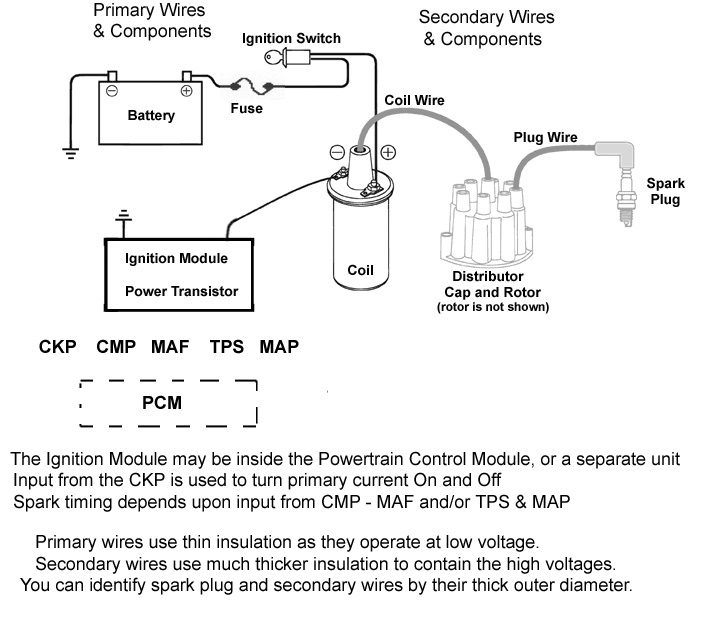
To identify the kind of ignition coil, the initial step is to know the definition of. The diagram of the basic ignition wiring illustrates a variety of connections and terminals. There are two primary and secondary connections. You need to determine the kind of coil you are using by testing the voltage at the primary terminal, S1. To determine if it is an A, C, or B coil, you should also test the resistance on S1’s.
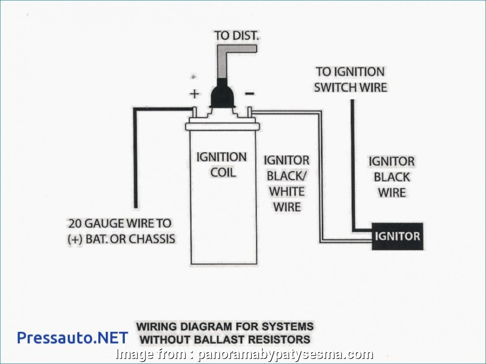
The lower-tension side of the coil should be connected to the chassis”negative. This is also the ground on an ignition wiring diagram. The high tension side provides positive directly the spark plugs. The aluminum body of the coil needs to be linked to the chassis to prevent it from being smothered but isn’t required. There are also connections of the positive and the negative coil’s terminals on an diagram of the ignition wiring. Sometimes, a defective ignition coil can be detected with a scan in an auto parts shop.
The black-and-white-striped wire from the harness goes to the negative terminal. The positive terminal is connected to the white wire, which has an black trace. The black wire connects with the contact breaker. To verify the wires’ connections, use a paperclip to lift them out of the housing. It is also important to ensure that the terminals are not bent.
Accessory terminals
Diagrams of ignition wiring show the various wires used to power the car’s various components. There are generally four color-coded terminals to each component. The accessories are red, the battery is yellow, the starter solenoid green. The “IGN terminal allows you to start your car, operate the wipers, and any other features that operate. This diagram demonstrates how to connect ACC and ST terminals with the rest of the components.
The terminal BAT is where the battery is. The electrical system won’t start without the battery. Furthermore, the switch won’t start. If you’re not sure of the exact location where the battery in your car is located, you can review the wiring diagram of your car to determine how to locate it. The accessory terminals in your car connect to the battery and the ignition switch. The BAT terminal is connected to the battery.
Some ignition switches feature a separate “accessory” location, which allows users can control their outputs without the ignition. Sometimes, a customer wants to make use of the auxiliary output separately from the ignition. The auxiliary output is connected to connect the connector in the same colors as your ignition, and then attaching it to the ACC terminal of the switch. Although this is a great option, there’s a thing you should know. Most ignition switches are set up to display an ACC status when the car’s in either the ACC or START positions.
Gallery of 12 Volt Points Ignition Wiring Diagram
Gallery of 12 Volt Points Ignition Wiring Diagram


