2002 Impala Ignition Switch Wiring Diagram – We’ll begin by looking at different kinds of terminals that are found on the ignition switch. These are the terminals that connect the Ignition, Coil, or Accessory. Once we know which terminals are used then we can recognize the various parts of the 2002 Impala Ignition Switch Wiring Diagram. We will also discuss the roles of the Ignition switch and the Coil. Then, we’ll talk about the roles of the ignition switch and Coil.
The ignition switch’s terminals
There are three different switches on an ignition switch that feed the battery’s voltage to several different destinations. The choke is powered by the first switch. The third switch regulates the ON/OFF of the ignition switch. Different manufacturers use different color codes for different conductors. This is discussed in a separate article. OMC utilizes this method. The ignition switch also includes an option to connect an tachometer.
Although some ignition switch terminals might not be original, the numbers of each may not be in line with the diagram. Check the electrical continuity to ensure that they are connected to the ignition switch correctly. This can be accomplished with a multimeter that is inexpensive. Once you are satisfied that the wires are in good order then you can connect the new connector. If you have an ignition switch that is supplied by the manufacturer, the wiring loom is different from the one you have in your car.
Before you can connect the ACC outputs to the auxiliary outputs of your car It is essential to understand the basics of these connections. The ACC, IGN and START terminals are the primary connection to the ignition switch. They also serve as the primary connections to your radio and stereo. The ignition switch controls the car’s engine. The terminals of older vehicles’ ignition switches are labeled by “ACC” and ST (for the individual magneto wires).
Terminals for coil
Understanding the terminology used is the initial step in determining what kind of ignition coil to choose. An understanding of the basic wiring diagram for ignition will provide you with a range of terminals and connections. The operating voltage of each coil differs. Therefore, it is important to first test the voltage at the S1 (primary terminal). You should also examine S1 for resistance to determine whether it is an A B, C, or coil.
The coil with low tension must be connected to the chassis’s less. This is the base of the ignition wiring. The high-tension component supplies positively direct to the spark plugs. The coil’s metal body needs to connect to the chassis to suppress the effect but is not electrically essential. The ignition wiring diagram will also demonstrate the connection of the positive and negative coil terminals. In certain instances scanning your local auto parts shop will help identify the malfunctioning ignition coils.
The black-and-white-striped wire from the harness goes to the negative terminal. The white wire is black and goes to the negative terminal. The black wire connects with the contact breaker. You can check the connections with a pencil to pull the wires out from the housing. Make sure you don’t bend the connectors.
Accessory terminals
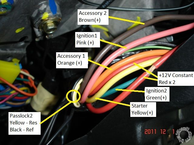
The ignition wiring diagrams illustrate the different wires that are utilized to power the vehicle’s various components. There are typically four colored terminals that correspond to each component. The accessories are red while the battery is yellow the starter solenoid is green. The “IGN” terminal can be used to turn on the car, turn on the wipers and other functions. The diagram illustrates how you can connect ACC or ST terminals as well as the rest.
The terminal referred to as BAT is the place where the battery is. Without the battery, the electrical system does not begin. A dead battery could make the switch not come on. If you’re not sure where your car’s battery is located, you can look at your wiring diagram to figure out where it is. The accessory terminals of your car are connected to the battery and ignition button. The BAT terminal is connected with the battery.
Some ignition switches feature an independent “accessory” position, in which users can control their outputs without the ignition. Customers may want to use the auxiliary output in addition to the ignition. In order for the auxiliary output be used, wire the connector to the same color as that of the ignition. Connect it to the ACC end of the switch. While this is an excellent option, there’s an crucial distinction. Most ignition switches are configured to be in an ACC position when the car is in the ACC position, but they’re in the START position when the vehicle is in the IGN position.
Gallery of 2002 Impala Ignition Switch Wiring Diagram
Gallery of 2002 Impala Ignition Switch Wiring Diagram


