Thwaites Dumper Ignition Switch Wiring Diagram – First, we will take a look at the various kinds of terminals found in the ignition switch. These are terminals for the Ignition, Coil, or Accessory. Once we have established the purpose of these terminals are then we can discover the various components of the Thwaites Dumper Ignition Switch Wiring Diagram. We’ll also discuss the different functions of the Ignition Switch and Coil. Then, we’ll turn our attention to the Accessory terminals.
Terminals for ignition switches
An ignition switch is made up of three different switches. They are responsible for supplying the battery’s energy to various locations. The first switch supplies power to the choke while the second switch controls the ON/OFF status of the ignition switch. Every manufacturer has its own color-coding system, which we will discuss in another article. OMC utilizes this method. The ignition switch comes with an option to connect a timer.
While the majority of the ignition switch terminals are not original, the numbers for each one may not be in line with the diagram. Examine the electrical continuity first to ensure they’re connected correctly to the ignition switch. This can be done with a multimeter that is inexpensive. Once you are satisfied that all wires are in good order then you can connect the new connector. If you have a factory-supplied ignition switch the wiring loom may be different from that in your car.
It is essential to know how the ACC outputs and the auxiliary outputs function to connect them. The ACC terminals and IGN terminals function as the primary connections to the ignition switch. The START and IGN connections are the most important connections for radio and stereo. The ignition switch is responsible to turn the engine of your car on and off. Older vehicles are identified with the alphabets “ACC”, “ST”, (for individual magneto cables) on their ignition switch terminals.
Terminals for coil
The language used to decide the kind and model of an ignition coil is the most important thing. The fundamental diagram of ignition wiring depicts various connections and terminals. There are two primary and one secondary. Each coil is operating at a certain voltage. The first step to determine which kind of coil you have is to check the voltage of S1 or the primary terminal. S1 should also undergo resistance testing to determine whether it are an A or B coil.
The coil’s low-tension component must be connected with the chassis positive. This is what is known as the ground for the wiring for ignition. The high tension side supplies positive directly the spark plugs. It is necessary for suppression purposes that the coil’s metallic body be connected to the chassis, however it isn’t essential. It is also possible to see the connections of the positive and negative coil’s terminals on an diagram of the ignition wiring. There could be an issue with the ignition coil that can be easily diagnosed by scanning it at an auto parts store.
The black-and-white-striped wire from the harness goes to the negative terminal. The white wire is the other one. It has a black trace on it and connects to the positive terminal. The black wire connects with the contact breaker. To confirm the connection, use a paperclip or a pencil to pull them out from the plug housing. It’s also essential to ensure that the terminals don’t bend.
Accessory Terminals
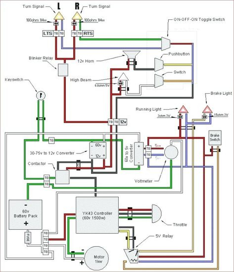
Diagrams of the ignition wiring depict the wires used to power various parts of the vehicle. There are usually four color-coded terminals that correspond to each component. Red is used to indicate accessories, yellow to the battery, and green for the starter solenoid. The “IGN terminal lets you start the car, manage the wipers, or any other functions. The diagram illustrates the connection of the ACC- and ST terminals.
The terminal called BAT is where the battery is connected. The electrical system can’t be started without the battery. A dead battery can make the switch not turn on. It is possible to look up your wiring diagram to determine where the batteries of your car are located. The ignition switch is connected to the car’s battery. The BAT terminal is connected to the battery.
Some ignition switches come with a separate “accessory” position, where users can control their outputs without using the ignition. Customers sometimes want an auxiliary output that can be operated independently of the ignition. Make use of the secondary output by connecting the connector to an ACC terminal on your switch that has the same color. While this is an excellent feature, there is one crucial distinction. The majority of ignition switches are configured to have an ACC status when the vehicle is at the ACC or START position.
Gallery of Thwaites Dumper Ignition Switch Wiring Diagram
Gallery of Thwaites Dumper Ignition Switch Wiring Diagram


