Golf Cart Ignition Wiring Diagram – Let’s first examine the different types and purposes of the terminals found on the ignition switches. They are the terminals used that are used for Coil, Ignition Switch, and Accessory. After we’ve identified the purpose of the terminals we will be able to identify the various parts of the ignition wiring. We’ll also go over the function of the Ignition switch and Coil. Then we’ll move on to the Accessory Terminals.
Terminals for ignition switches
An ignition switch contains three switches that supply the battery’s power to various locations. The first one supplies power to the choke when pushed, and the second is the ignition switch’s ON/OFF position. Different manufacturers have different color-coding schemes for different conductors. This will be covered in a separate article. OMC uses this system. The ignition switch comes with an option to connect the Tachometer.
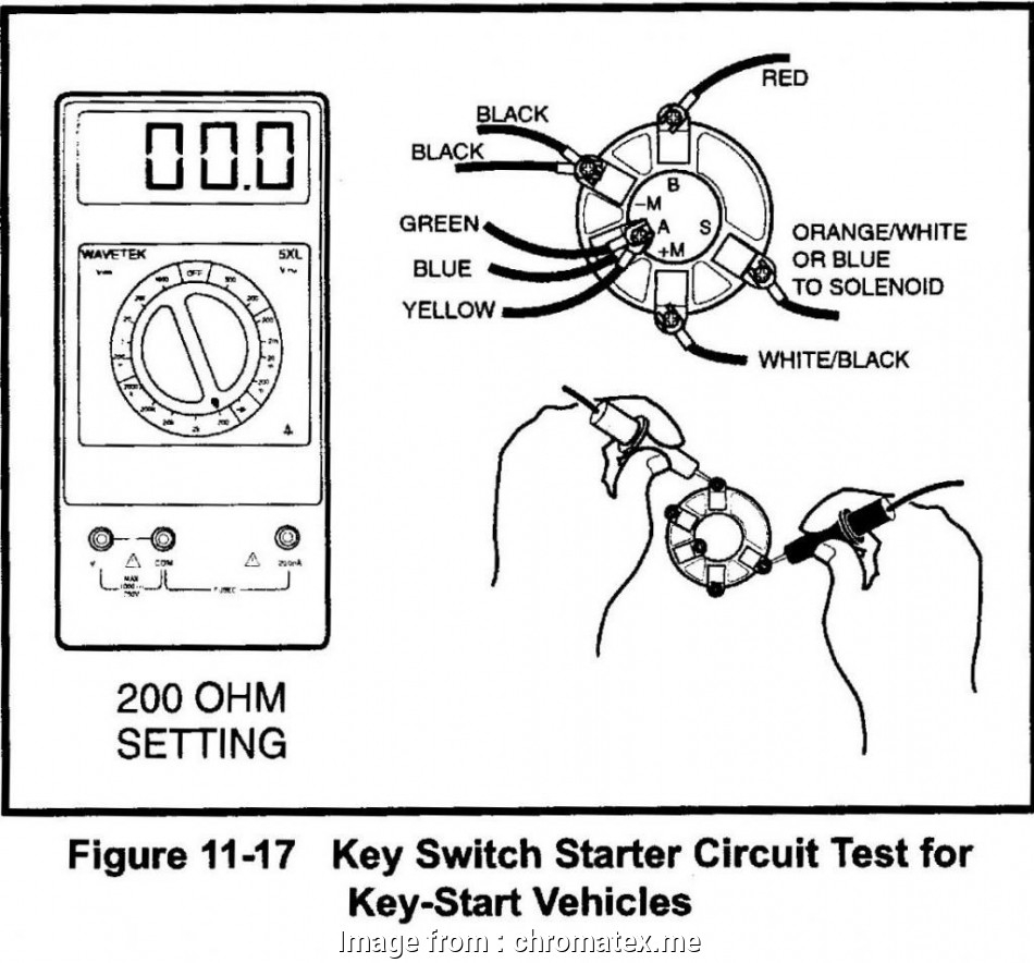
Although the majority of ignition switch terminals are duplicated, the numbers might not match the diagram. Examine the continuity of the wires first to make sure they are correctly plugged in the ignition switch. A multimeter is an excellent tool to check the continuity. When you’re happy with the quality of the connection it’s time to connect the new connector. The wiring loom used for the ignition switch supplied by the factory will be different from the one in your car.
First, understand the differences between ACC and auxiliary outputs. The ACC and IGN terminals are the default connections on your ignition switch. the START and IGN terminals are the principal connections for radio and stereo. The ignition switch is accountable to turn the engine of your car on and off. The terminals of older cars ignition switches are identified with “ACC” as well as ST (for individual magneto wires).
Terminals for coil
Understanding the terminology that is used is the initial step in finding out the right type of ignition coil. There are a variety of connections and terminals in an ignition wiring schematic that include two primary and two secondary. The coils come with a distinct operating voltage, and the first method of determining what type you’ve got is to check the voltage on S1, the main terminal. S1 must also be subjected to resistance testing to determine whether it’s a Type A or B coil.
The chassis’ negative needs to be connected to the low-tension side. This is the wiring diagram you will see in the wiring diagram. The high tension part supplies positively directly to the spark plugs. The coil’s metal body needs to connect to the chassis to prevent it from being smothered however it isn’t electrically necessary. The ignition wiring diagram will also show how to connect the positive coil terminals. Sometimes, a damaged ignition coil is identified by a scan done in an auto parts shop.
The black-and-white-striped wire from the harness goes to the negative terminal. The positive terminal receives the white wire with the black trace. The black wire is connected to the contact breaker. It is possible to remove the black wire from the housing of the plug with a paper clip in case you are uncertain about the connections. It is also important to see that the terminals aren’t bent.
Accessory Terminals
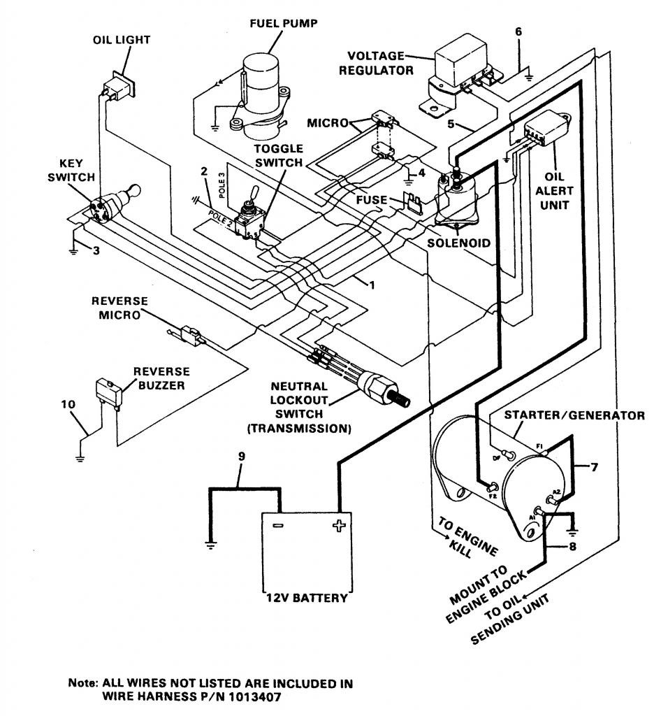
Ignition wiring diagrams depict the different wires used to power various components. There are usually four terminals with color codes that are connected to the respective component. The red color is used for accessories, yellow is for the battery, and green is for the starter solenoid. The “IGN” terminal is used to start the car, controlling the wipers and various other functions. The diagram illustrates how you can connect ACC or ST terminals and the rest.
The terminal BAT is where the battery is. Without the battery the electrical system will not get started. Furthermore, the switch won’t start. It is possible to view the wiring diagram of your car to see where your car’s batteries are located. The accessory terminals of your car connect to the ignition switch, as well as the battery. The BAT terminal connects to the battery.
Certain ignition switches come with an accessory setting where users can adjust their outputs and control them without needing to use the ignition. Sometimes, customers wish to use an auxiliary output that is separate from the ignition. To allow the auxiliary output to be used, connect the connector with the same color as that of the ignition. Connect it to the ACC end of the switch. This is a useful feature, however there’s an important difference. Most ignition switches are configured to operate in the ACC position when the car is in the ACC position, while they’re set to the START position when the vehicle is in the IGN position.
Gallery of Golf Cart Ignition Wiring Diagram
Gallery of Golf Cart Ignition Wiring Diagram


