12v Ignition Coil Wiring Diagram – We’ll begin by looking at different types terminals found on the ignition switch. They include terminals for Coil, Ignition Switch, and Accessory. When we have a clear understanding of the purpose of each type of terminal, we are able to identify the parts of the ignition wiring. We will also cover the roles of both the Ignition Switch and Coil. After that, we’ll turn our attention to the Accessory terminals.
Terminals for the ignition switch
There are three separate switches in the ignition switch, and they feed the battery’s voltage to various places. The ON/OFF position of the ignition switch is controlled by the first switch, which supplies power to the choke when it’s pulled. Every manufacturer has its own color-coding system, which we’ll discuss in a subsequent article. OMC utilizes the same system. A connector is also included inside the ignition switch to allow attaching the to a tachometer.
While the majority of ignition switch terminals do not come in original form The numbering might not be in line with the diagram. You should first check the electrical continuity to ensure that they are connected to the correct ignition switch. This can be done using a simple multimeter. After you’re sure that all wires are running in good harmony, you can attach the new connector. If you are using a factory-supplied ignition switch the wiring loom will be distinct from the one that is in your car.
Knowing how the ACC outputs connect to the other outputs of your car is vital. The ACC, IGN and START terminals are the primary connection to the ignition switch. They also serve as the primary connections to the radio and stereo. The ignition switch switches the engine of your car ON and OFF. Older vehicles have ignition switch terminals labeled “ACC” or “ST” (for individual magnetowires).
Terminals for coil
The first step in determining the type of ignition coil is to understand the terms that is used. A basic ignition wiring layout will reveal a variety of connections and terminals. You need to determine the type of coil you have by testing the voltage at the primary terminal, S1. S1 should be tested for resistance in order to identify if the coil is Type A, B, and/or C.
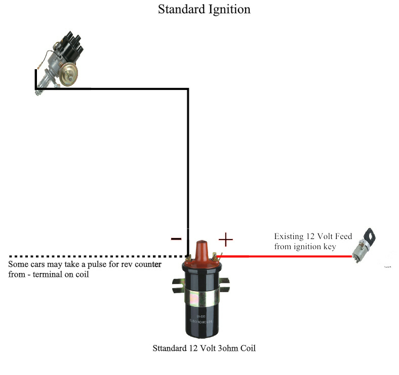
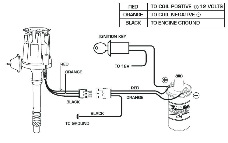
The low-tension side of the coil needs to be connected to the chassis the negative. This is what is known as the ground for the wiring for ignition. The high-tension side supplies the positive power directly to the spark plugs. For suppression purposes the coil’s metal body must be connected to the chassis. This is not necessary to use electricity. The wiring diagram of the ignition will show you how to connect the two terminals of the positive or negative coils. Sometimes, a defective ignition coil can be identified with a scan at an auto parts shop.
The black-and-white-striped wire from the harness goes to the negative terminal. Positive terminal gets the second white wire, which includes a black trace. The black wire is connected to the contact breaker. If you’re unsure of the connections of the two, try using the clip of a paperclip to remove them from the plug housing. It’s also essential to make sure that the terminals do not bend.
Accessory terminals
Diagrams of the ignition wiring illustrate the wires used to provide power to various components of the car. There are usually four color-coded terminus for each component. Red refers to accessories, yellow the battery, and green the starter solenoid. The “IGN terminal lets you start the car, control the wipers, and any other features that operate. The diagram shows how you can connect the ACC and ST terminals to the rest of the components.
The terminal BAT holds the battery. The electrical system won’t start without the battery. The switch won’t turn off if the battery isn’t present. It is possible to look up the wiring diagram of your car to see the location of your car’s batteries. placed. The accessory terminals in your vehicle are connected to the battery and the ignition button. The BAT connector is connected to your battery.
Certain ignition switches have an additional position. It allows users to access their outputs from another location without the ignition. Customers may want to utilize the auxiliary output independently of the ignition. The auxiliary output is used by wiring the connector in the same colors as the ignition and connecting it to the ACC terminal of the switch. While this is an excellent feature, there’s something you need to know. The majority of ignition switches have an ACC position when the vehicle is in the ACC however, they’ll be in the START position if the vehicle is IGN.
Gallery of 12v Ignition Coil Wiring Diagram
Gallery of 12v Ignition Coil Wiring Diagram


