Compu-fire Ignition Wiring Diagram – First, let’s look at the different terminals on the ignition switch. They are the terminals used that are used for Coil, Ignition Switch, and Accessory. Once we know what these terminals do then we can identify the different parts in the ignition wiring. We will also talk about the functions as well as the Coil. Then we’ll proceed to the Accessory Terminals.
Terminals for the ignition switch
Three switches are found on an ignition switch. Each of these three switches is able to feed the battery’s voltage to several different locations. The first switch supplies the choke with power, while the second toggles the ON/OFF status of the ignition switch. Different manufacturers have their own color-coding system for the various conductors, which is documented in another article. OMC follows this system. The connector permits the attachment of a speedometer the ignition switch.
Although the majority of ignition switch terminals can be duplicated, the numbers might not be consistent with the diagram. Verify the integrity of the wires first to ensure that they are correctly plugged in the ignition switch. This can be checked using a simple multimeter. Once you’re satisfied with the connection, you can place the new connector. If your vehicle is equipped with an ignition switch installed, the wiring diagram will differ.
Before connecting the ACC outputs to the auxiliary outputs of your car It is essential to be familiar with the fundamentals of these connections. The ACC and IGN terminals are the default connections for the ignition switch. the START and IGN terminals are the principal connections to the stereo and radio. The ignition switch turns the car’s engine on and OFF. Older cars are identified with the initials “ACC”, “ST”, (for individual magneto cables) at the ignition switch’s terminals.
Terminals for coil
The language used to decide the model and type of an ignition coil is the first thing. In a basic ignition wiring diagram there are various connections and terminals, such as two primary and two secondary. It is essential to identify the kind of coil you are using by testing the voltage at the primary terminal, called S1. S1 should also undergo resistance tests to determine if it’s an A or B coil.
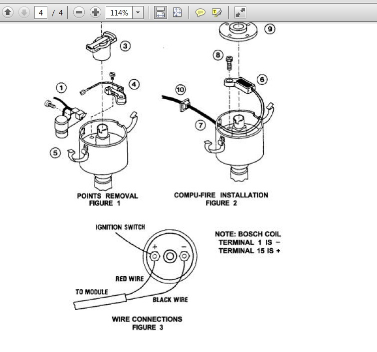
The low-tension coil side must be connected at the chassis’s less. This is the base of the wiring for ignition. The high tension part supplies positive directly the spark plugs. The body of the coil has to be connected to the chassis for suppression purposes however it isn’t electrically required. The diagram for the ignition wiring will also reveal the connections between the negative and positive coil’s terminals. In some cases it is possible to find a malfunctioned ignition coil is identified by scans at an auto parts store.
The black-and-white-striped wire from the harness goes to the negative terminal. The positive terminal is connected to the white wire with an black trace. The black wire is connected to the contactbreaker. To verify the connections between the two wires employ a paperclip to remove them off the housing. Also, see that the terminals aren’t bent.
Accessory Terminals
Diagrams of ignition wiring show the various wires used to power the car’s various parts. There are usually four colored terminals that correspond to the respective component. The accessories are red while the battery is yellow and the starter solenoid green. The “IGN” terminal is used to turn on the car , and also to operate the wipers, as well as other operating features. This diagram demonstrates how to connect ACC and ST terminals with the rest of the components.
The terminal BAT is the connector for the battery. The electrical system won’t start when the battery isn’t connected. The switch will not turn on if there is no battery there. The wiring diagram will show you where to find the battery of your car. The accessory terminals in your vehicle are connected to the battery and the ignition switch. The BAT terminal is connected to the battery.
Some ignition switches have the “accessory” position that allows users to control their outputs without needing to utilize the ignition. Some customers may prefer to utilize the auxiliary output separately from the ignition. The auxiliary output could be connected to connect the connector with the same colors as the ignition, and then connecting it to the ACC terminal of the switch. This feature is convenient, but it has one major distinction. Most ignition switches are set to be in an ACC position when the vehicle is in the ACC position, but they’re in the START position when the car is in the IGN position.
Gallery of Compu-fire Ignition Wiring Diagram
Gallery of Compu-fire Ignition Wiring Diagram


