12v Ignition Switch Wiring Diagram – Let’s first examine the different types and purposes of the terminals found in the ignition switches. These terminals are for the Ignition button, Coil and Accessory. Once we’ve determined the function of these terminals, we can determine the various components of the ignition wiring. We will also discuss the roles of the Ignition switch and Coil. Then, we’ll turn our attention to Accessory terminals.
Terminals for ignition switch
The ignition switch is comprised of three switches that supply the battery’s current to various locations. The first switch is the one that supplies power to the choke, while the second toggles the on/off status of the ignition switch. Different manufacturers use different color codes for different conductors. This is discussed in another article. OMC follows this approach. A connector is also included inside the ignition switch for attaching the tachometer.
Although many ignition switch terminals do not come in original form, the numbering may not match that of the diagram. Check the integrity of the wires to see if they are connected to the correct ignition switch. A multimeter is a good tool to check the continuity. When you’re satisfied with the continuity of your wires, you’ll be able to connect the new connector. If you are using an ignition switch that is supplied by the manufacturer the wiring loom may be different from that used in your vehicle.
For connecting the ACC outputs to the auxiliary outputs of your car, you need to understand the way these two connections function. The ACC, IGN and START terminals are your default connections to the ignition switch. They also serve as the primary connections to your radio and stereo. The ignition switch is responsible for turning the car’s engine to and off. In older vehicles the ignition switch’s terminals are marked with the alphabets “ACC” and “ST” (for distinct magnetic wires).
Terminals for coil
Understanding the terminology used is the first step towards determining what type of ignition coil. A basic ignition wiring diagram will show a variety of connections and terminals, comprising two primary and two secondary. The voltage that operates on each coil differs. It is important to first test the voltage at the S1 (primary terminal). S1 must also go through resistance testing to determine if it is an A or B coil.
The coil with low tension must be connected to the chassis’ minus. This is the ground in the diagram of the ignition wiring. The high tension side supplies positively directly to the spark plugs. To reduce the noise the coil’s metal body must be connected with the chassis. It is not required for electrical use. It is also possible to see the connections of the positive and negative coil’s terminals on an diagram of the ignition wiring. Sometimes, a malfunctioning ignition coil can be detected by a scan done at an auto repair shop.
The black-and-white-striped wire from the harness goes to the negative terminal. The positive terminal also gets the second white wire, which includes a black trace. The black wire goes to the contact breaker. To check the connections between the two wires use a paperclip and lift them from the housing. Make sure you don’t bend the connectors.
Accessory terminals
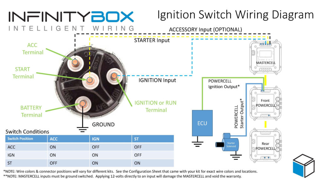
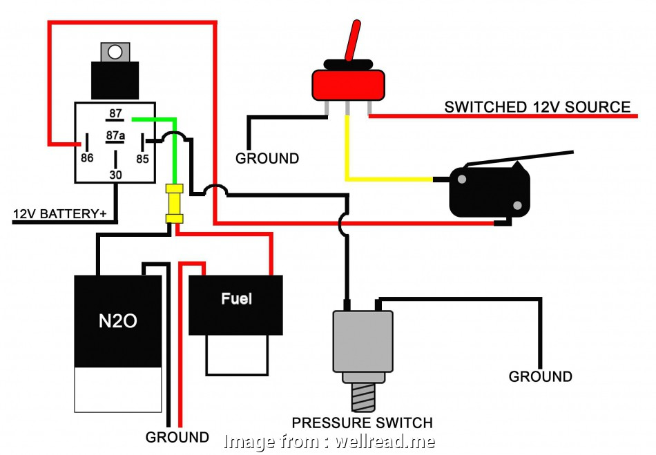
The diagrams for ignition wiring illustrate the wires used to power the vehicle’s electrical supply. There are generally four color-coded terminals that correspond to each component. Accessories are red, the battery is yellow the starter solenoid green. The “IGN” terminal can be used to start the car and operate the wipers and other operating functions. The following diagram shows how to connect the ACC terminal as well as the ST terminals to the other components.
The battery is attached to the terminal named BAT. Without the battery, the electrical system does not start. Additionally, the switch will not be able to turn on without the battery. To find your car’s battery, check your wiring diagram. The ignition switch is linked to the car’s battery. The BAT connector is connected to your battery.
Some ignition switches offer an additional “accessory position” which allows users to modify their outputs independent of the ignition. Sometimes, customers wish to make use of the auxiliary output separate from the ignition. You can use the additional input by connecting the connector to the ACC terminal. This option is useful however it does have one significant difference. A lot of ignition switches can be programmed to have an ACC location when the car has moved into the ACC position. They’ll also be in START mode after the vehicle has been moved into the IGN position.
Gallery of 12v Ignition Switch Wiring Diagram
Gallery of 12v Ignition Switch Wiring Diagram


