1997 Ford Ranger Ignition Wiring Diagram – The first step is to take a look at the different kinds of terminals that are used on the ignition switch. These are the terminals used that are used for Coil, Ignition Switch, and Accessory. Once we know the terminals that are utilized and which ones are not, we can identify the different components of the 1997 Ford Ranger Ignition Wiring Diagram. Then, we will discuss the functions as well as the Coil. Then, we’ll turn our attention to the Accessory terminals.
The ignition switch’s terminals
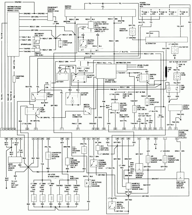
There are three different switches in an ignition switch that transmit the battery’s current voltage to a variety of destinations. The first switch powers the choke. The third switch regulates the ON/OFF function of the ignition switch. Different manufacturers use different colour-coding systems that correspond to the conductors. OMC uses this method. The connector permits the connection of a speedometer to the ignition switch.
While the majority of ignition switch terminals do not have an original number, they may be equipped with a different number. Check the electrical continuity to determine if they’re connected to the ignition switch correctly. A multimeter is an excellent instrument to verify the continuity. Once you’re satisfied with the continuity then you can connect the new connector. The wiring loom in a factory-supplied ignition system switch is different.
It is important to know the differences between ACC and auxiliary outputs. The ACC, IGN and START terminals are the default connections to the ignition switch. They also function as the primary connections to your radio and stereo. The ignition switch acts as the engine’s off/on button. The terminals of the ignition switch on older vehicles are marked with the alphabets “ACC” as well as “ST” (for the individual magneto wires).
Terminals for coil
The terms used to define the kind and model of an ignition coil is the primary thing. A basic ignition wiring diagram will reveal a variety of terminals and connections, comprising two primary and two secondary. Each coil has an operating voltage. The first step to determine which kind of coil you’re using is to examine the voltage of S1 or the primary terminal. S1 should be examined for resistance to determine if the coil is Type A, B, and/or C.
The coil’s low-tension component must be connected with the chassis positively. This is what’s called the ground on the ignition wiring diagram. The high-tension component supplies positively directly to the spark plugs. The coil’s metal body needs to be connected to the chassis for suppression purposes, but it is not electrically essential. You will also see the connections of the positive and the negative coil’s terminals on an ignition wiring diagram. In some cases you’ll discover that an ignition coil that is malfunctioning is identified by scans in an auto parts store.
The black-and-white-striped wire from the harness goes to the negative terminal. The other white wire has a black trace on it, and it connects to the positive terminal. The black wire connects to the contactbreaker. You can check the connections with a pencil to pull the wires out of the housing. It is also important to ensure that the terminals do not bend.
Accessory Terminals
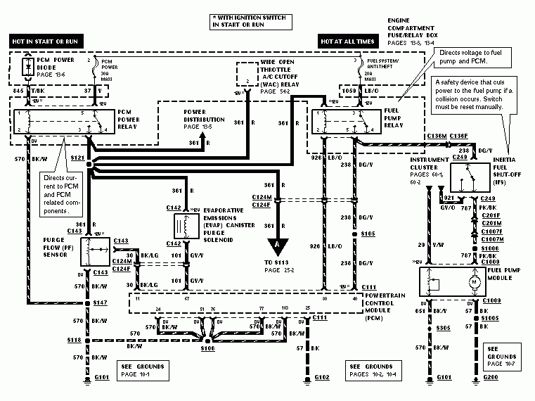
The ignition wiring diagrams illustrate the various wires used to power the car’s various components. There are usually four different colored terminals for each component. The accessories are colored red, the battery is yellow the starter solenoid is green. The “IGN” terminal can be used to start the car , and also to operate the wipers, as well as other operating features. The diagram illustrates how to connect ACC or ST terminals as well as the rest.
The battery is connected to the terminal whose name is BAT. Without the battery the electrical system can not begin. Furthermore, the switch doesn’t turn on. A wiring diagram can inform you where to find the battery of your car. The accessory terminals in your car are connected to the ignition switch and the battery. The BAT terminal is connected to the battery.
Some ignition switches offer the option of an “accessory position” that allows users to adjust their outputs independently of the ignition. Sometimes, customers would like the output of the auxiliary to be used independently from the ignition. To use the auxiliary output, connect the connector with identical colors to the ignition and connect it to the ACC terminal on the switch. This is a useful feature, however there’s one important distinction. A majority of ignition switches feature the ACC position when your car is in the ACC mode, and a START position when it is in IGN.
Gallery of 1997 Ford Ranger Ignition Wiring Diagram
Gallery of 1997 Ford Ranger Ignition Wiring Diagram


