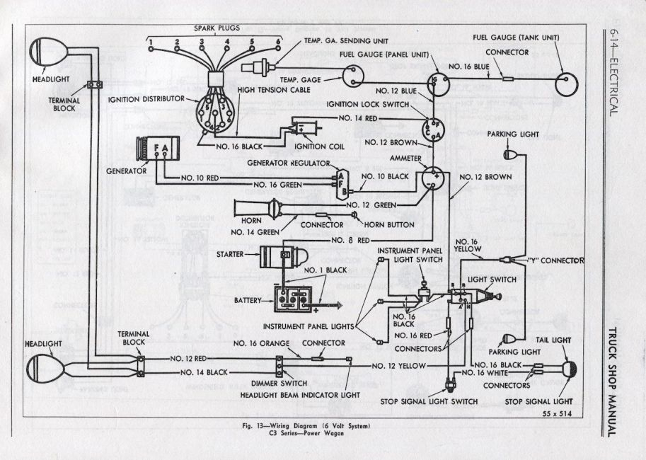
1955 6 Volt Ignition Wiring Diagram – We’ll begin by looking at different kinds of terminals that are found on an ignition switch. The terminals are the Ignition switch and Coil and the Accessory. Once we know the terminals that are utilized then we can recognize the various parts of the 1955 6 Volt Ignition Wiring Diagram. We’ll also be discussing the function of the Ignition switch and Coil. Then, we’ll turn our attention to Accessory terminals.
The ignition switch’s terminals
Three switches are located on the ignition switch. Each of these switches is able to feed the battery’s voltage to several different places. The first one supplies power to the choke when it is pushed. The second is the switch that controls the ignition’s ON/OFF positions. Different manufacturers use different color codes for various conductors. This is discussed in a different article. OMC utilizes this method. The ignition switch also includes a connector for adding a timer.
Even though some ignition switch terminals don’t come in original form The numbering might not match that of the diagram. To ensure that your wires are properly plugged in to the switch you must verify their continuity. A multimeter that is inexpensive can assist you in this. Once you are satisfied that all wires are in good order then you can connect the new connector. If you’re using an ignition switch that is supplied by the manufacturer, the wiring loom is different from that you have in your car.
For connecting the ACC outputs to the auxiliary outputs of your vehicle, you have to understand how these two connections work. The ACC, IGN and START terminals are your default connection to the ignition switch. They also serve as the primary connections to the radio and stereo. The ignition switch switches the car’s engine on and off. On older vehicles the ignition switch’s terminals are identified with the alphabets “ACC” as well as “ST” (for distinct magnet wires).
Terminals for coil
The terms used to define the model and type of an ignition coil is the most important thing. You’ll see a number of connections and terminals on an ignition wiring schematic which includes two primary and two secondary. You must determine the type of coil you have by testing the voltage on the primary terminal, called S1. To determine if the coil is an A, C, or B coil it is recommended to also test the resistance on S1’s.
The chassis’ negative should be connected to connect the coil’s low-tension side. This is the ground in the wiring diagram for ignition. The high-tension side provides the spark plugs with positive. The coil’s metal body needs to connect to the chassis to suppress the effect however it isn’t electrically essential. The wiring diagram of the ignition will demonstrate how to connect the terminals of the negative or positive coils. In some instances you’ll discover that an ignition coil that is malfunctioning is identified by scanning at an auto parts shop.
The black-and-white-striped wire from the harness goes to the negative terminal. The negative terminal is served by the black trace that’s joined to the white wire. The contact breaker is connected to the black wire. To verify the wires’ connections, employ a paperclip to lift them out of the housing. It’s also crucial to make sure that the terminals don’t bend.
Accessory Terminals
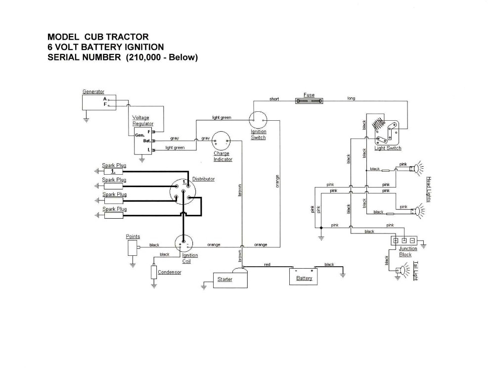
The ignition wiring diagrams illustrate the different wires that power the various components of the car. There are generally four terminals with color codes that are connected to the component. Red is used to indicate accessories, yellow is the battery, and green the starter solenoid. The “IGN terminal lets you start the car, control the wipers, or any other operation features. The diagram shows how you can connect the ACC and ST terminals to the rest of the components.
The terminal BAT is the connector for the battery. The electrical system will not start without the battery. In addition, the switch doesn’t turn on. It is possible to refer to your wiring diagram if you are not sure where the batteries of your car are located. The accessory terminals in your vehicle are connected to the battery and the ignition button. The BAT terminal connects to the battery.
Some ignition switches have the “accessory” setting that allows users to control their outputs without needing to turn on the ignition. Sometimes, customers want to make use of the auxiliary output separately from the ignition. It is possible to use the auxiliary input by connecting it to the ACC terminal. While this is an excellent option, there’s a thing you should know. The majority of ignition switches are configured to display an ACC status when the vehicle is at either the ACC or START position.
Gallery of 1955 6 Volt Ignition Wiring Diagram
Gallery of 1955 6 Volt Ignition Wiring Diagram


