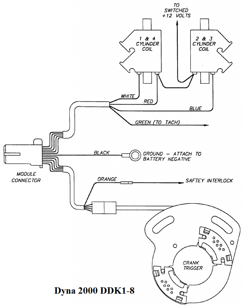
Shovelhead Electronic Ignition Wiring Diagram – We will first look at the different types of terminals in the ignition switch. The terminals are the Ignition switch as well as the Coil and the Accessory. Once we have identified what these terminals do, we will be able to identify the various parts of the ignition wiring. We will also talk about the functions and the Coil. Then, we’ll talk about the roles of the Ignition switch and Coil.
Terminals for ignition switch
An ignition switch is made up of three switches. They are the ones that supply the battery’s energy to various locations. The first switch provides power to the choke, while the second switch controls the ON/OFF status of the ignition switch. Different manufacturers employ different color codes for different conductors. This is described in a different article. OMC uses this method. The ignition switch is also equipped with an option to connect an Tachometer.
While most ignition switch terminals are not original, the numbering for each might not be consistent with the diagram. First, check the continuity of all wires to ensure they are correctly plugged into the ignition switches. This can be checked using an inexpensive multimeter. After you’re satisfied with the continuity, you can place the new connector. If your car is equipped with an original ignition switch supplied by the factory (or wiring loom) The wiring loom will differ from that of the car.
For connecting the ACC outputs to the auxiliary outputs of your car, you’ll need to first understand how these two connections work. The ACC, IGN and START terminals are the default connection to the ignition switch. They also serve as the primary connections to your radio and stereo. The ignition switch is the one that controls the engine of your car. In older vehicles, the ignition switch terminals are marked with the alphabets “ACC”, and “ST” (for individual magnetic wires).
Terminals for coil
To identify the kind of ignition coil, the first step is to learn the definition of. An ignition wiring diagram will show a variety of terminals and connections comprising two primary and two secondaries. The coils are equipped with a particular operating voltage. The initial method of determining what type you’ve got is to check the voltage on S1, the primary terminal. S1 must be tested for resistance in order to identify if the coil is Type A, B, and/or C.
The coil’s low-tension component must be connected with the chassis positive. This is what you see in the wiring diagram. The high tension part supplies positive power directly to the spark plugs. To reduce the noise, the coil’s body metal must be connected with the chassis. It’s not necessary to use electricity. The ignition wiring diagram will also indicate how to connect the positive coil terminals. In some cases it is recommended to conduct a scan at the local auto parts store will be able to diagnose the malfunctioning ignition coils.
The black-and-white-striped wire from the harness goes to the negative terminal. The white wire also is black with a trace on it and it connects to the positive terminal. The black wire connects to the contact breaker. If you’re not sure about the connection between both, you can use a paper clip to remove them from the housing of the plug. Make sure that the connectors do not bend.
Accessory terminals
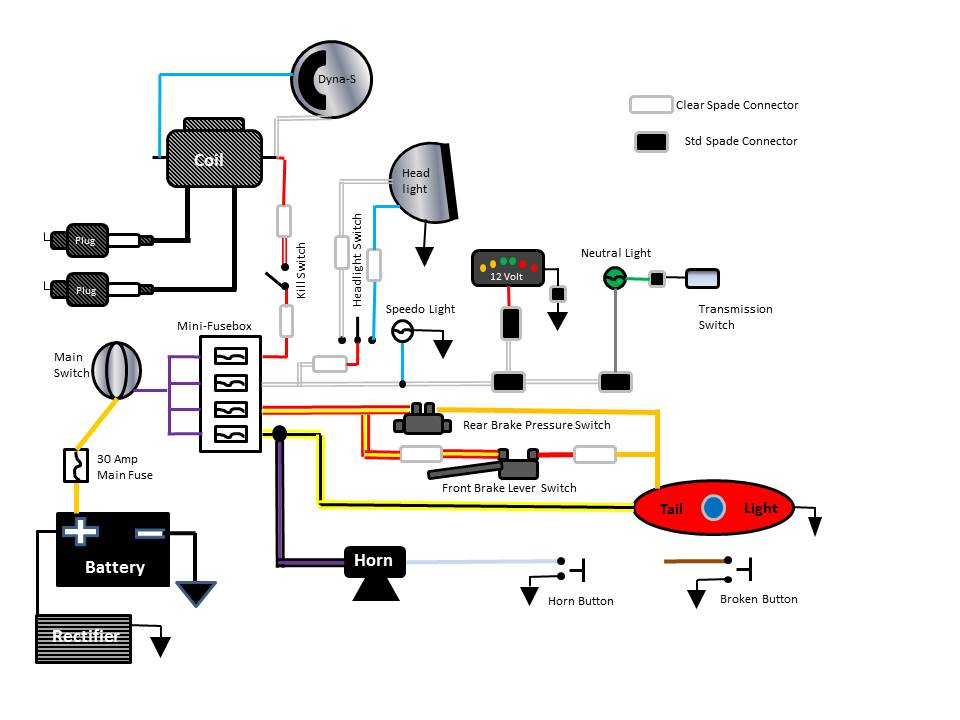
Ignition wiring diagrams show the different wires that are used to power the car’s various parts. There are typically four colors of terminals connected to each part. Red refers to accessories, yellow to the battery and green is the starter solenoid. The “IGN” terminal is used to start the vehicle and control the wipers, as well as other operating features. The diagram below illustrates how to connect the ACC terminal as well as the ST terminals to various components.
The battery is attached to the terminal whose name is BAT. The electrical system is not able to begin without the battery. A dead battery can make the switch not turn on. To find the battery in your car, check your wiring diagram. Your car’s accessory terminals are connected to the ignition switch as well as the battery. The BAT terminal is connected to the battery.
Some ignition switches come with an additional “accessory position” that lets users modify their outputs independent of the ignition. Sometimes, customers may wish to utilize the auxiliary input independently of the ignition. You can use the additional output by connecting it to an ACC terminal on the switch that has the same color. This is an excellent option, but there’s an important difference. Some ignition switches are programmed to have an ACC position once the car has moved into the ACC position. They also will be in the START mode after the vehicle has been entered the IGN position.
Gallery of Shovelhead Electronic Ignition Wiring Diagram
Gallery of Shovelhead Electronic Ignition Wiring Diagram


