1965 Ford Mustang Ignition Switch Wiring Diagram – Let’s begin by looking at the different types of terminals on the ignition switch. These are terminals for the Ignition, Coil, or Accessory. Once we’ve determined the function of the terminals we will be able to determine the various components of the ignition wiring. We’ll also discuss the roles of both the Ignition Switch and the Coil. Next, we’ll discuss the roles of the Ignition switch as well as Coil.
Terminals for ignition switches
An ignition switch is composed of three switches. They are the ones that supply the battery’s power to various locations. The choke is powered by the first switch. The second switch controls the ON/OFF function of the ignition switch. Every manufacturer has its unique color-coding system, which we’ll go over in a separate article. OMC utilizes this method. Connectors can be connected to the ignition switch to add a digital Tachometer.
Although some ignition switch terminals don’t have the original design, the numbering may not match the diagram. The first step is to check the continuity of all the wires to ensure that they are properly connected to the ignition switches. This can be accomplished with a simple multimeter. When you’re satisfied with the continuity of the wires, then you’ll be able install the new connector. If you have an ignition switch supplied by the manufacturer the wiring loom may be distinct from the one that is in your car.
First, understand the differences between the ACC and secondary outputs. The ACC, IGN and START terminals are your default connection to the ignition switch. They also serve as the main connections to the radio and stereo. The ignition switch is the one that controls the engine of your car. Older vehicles are identified with the initials “ACC”, “ST”, (for individual magneto cables) at the ignition switch’s terminals.
Terminals for coil
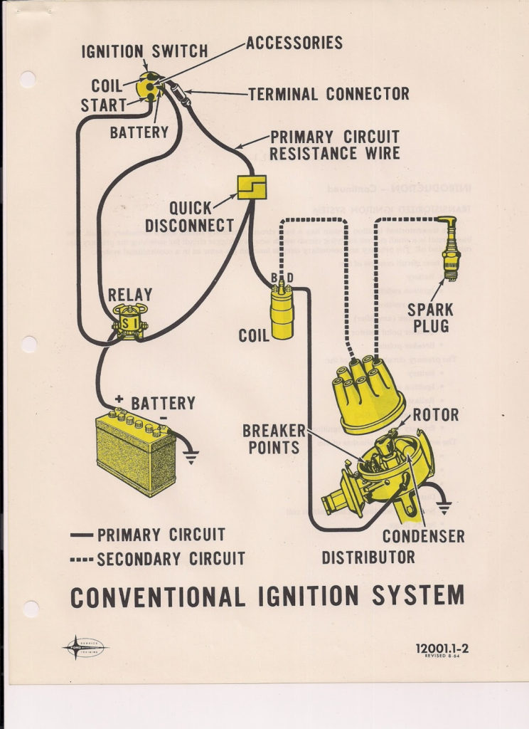
Understanding the terminology used is the initial step to determining what kind of ignition coil to choose. In a simple diagram of the wiring for ignition you’ll see a number of different connections and terminals, such as two primary and two secondary. You must determine the type of coil that you are using by testing the voltage on the primary terminal, S1. S1 must be checked for resistance to identify if the coil belongs to type A, B or C.
The coil’s low-tension component must be connected with the chassis’ positive. This is what you see on the diagram of wiring. The high-tension component connects the spark plugs to a positive. The aluminum body of the coil needs to be linked to the chassis for suppression however it’s not electrically required. The wiring diagram of the ignition will demonstrate how to connect the two terminals of the positive and negative coils. In certain instances it is recommended to conduct a scan at your local auto parts shop can help you identify defective ignition coils.
The black-and-white-striped wire from the harness goes to the negative terminal. The other white wire is black with a trace on it, and it goes to the positive terminal. The black wire is connected to the contact breaker. To verify the connections between the two wires use a paperclip and lift them off the housing. Make sure you check that the terminals have not been bent.
Accessory terminals
Diagrams of the ignition wiring depict the wires that supply power to different parts of the car. There are generally four colors of terminals connected to each part. The red color is used for accessories and yellow is for the battery, while green is for the starter solenoid. The “IGN terminal lets you start your car, operate the wipers or other features that operate. This diagram demonstrates how to connect ACC and ST terminals to the rest of components.
The terminal referred to as BAT is where the battery is connected. Without the battery, the electrical system does not get started. The switch will not turn on if the battery isn’t there. It is possible to refer to your wiring diagram if you are uncertain about where the car’s batteries are located. The accessory terminals in your vehicle are connected to the battery and ignition button. The BAT terminal is connected to the battery.
Certain ignition switches come with an “accessory” position that allows users to control their outputs , without needing to utilize the ignition. Customers may want to use the auxiliary output independently of the ignition. The auxiliary output is connected by wiring the connector in the same colors as the ignition, and then attaching it to the ACC terminal of the switch. This convenience feature is great however, there’s one distinction. The majority of ignition switches are set to be in an ACC position when the car is in the ACC position, but they’re set to the START position when the car is in the IGN position.
Gallery of 1965 Ford Mustang Ignition Switch Wiring Diagram
Gallery of 1965 Ford Mustang Ignition Switch Wiring Diagram


