1965 Mustang Ignition Wiring Diagram – The first step is to take a look at the different kinds of terminals on the ignition switch. These include the terminals that are for the Ignition switch, Coil, and Accessory. Once we’ve established the purpose of these terminals, we will be able to recognize the various parts of the ignition wiring. We will also talk about the functions and the Coil. Then we’ll discuss the Accessory Terminals.
The terminals of the ignition switch
Three switches are located on the ignition switch. Each of these three switches is able to feed the battery’s voltage to various places. The choke is powered by the first switch. The third switch regulates the ON/OFF of the ignition switch. Different manufacturers have distinct colors-coding systems to match the conductors. OMC follows this system. The ignition switch also includes a connector for adding an timer.
Although most ignition switch terminals are duplicated, the numbers might not be in line with the diagram. You should first check the electrical continuity to determine if they’re plugged into the correct ignition switch. A cheap multimeter can help you do this. After you’re satisfied with the quality of the connection then you can connect the new connector. If your car is equipped with an original ignition switch supplied by the factory (or a wiring loom), the wiring loom will differ from that in the car.
Knowing how the ACC outputs are connected to the other outputs of your car is vital. The ACC and IGN terminals are the default connections on your ignition switch. the START and IGN terminals are the primary connections to the stereo and radio. The ignition switch regulates the engine in your car. Older vehicles are identified with the alphabets “ACC”, “ST”, (for individual magneto cables) on their ignition switch terminals.
Coil terminals
The language used to decide the model and type of an ignition coil is the most important thing. In a simple diagram of the wiring for ignition there are various connections and terminals, such as two primary and two secondary. Each coil is equipped with a distinct operating voltage. To determine which type of coil you own the first step is to determine the voltage at S1, which is the primary terminal. You should also test S1 for resistance in order to determine if it’s a Type A or B coil.
The chassis’ negative needs to be connected to the low-tension side. This is the ground of the wiring for ignition. The high-tension side is a positive connection to the sparkplugs. The metal body of the coil needs to connect to the chassis for suppression purposes, but it is not electrically essential. The diagram of the ignition wiring will also demonstrate how to connect the negative and positive coil terminals. There could be an ignition coil problem that is easily identified by looking it up at the auto parts shop.
The black-and-white-striped wire from the harness goes to the negative terminal. The positive terminal also receives the second white wire, which is black in its trace. The contact breaker is connected to the black wire. If you’re not certain about the connections between the twowires, use the clip of a paperclip to remove them from the plug housing. It’s also crucial to ensure that the terminals aren’t bent.
Accessory terminals
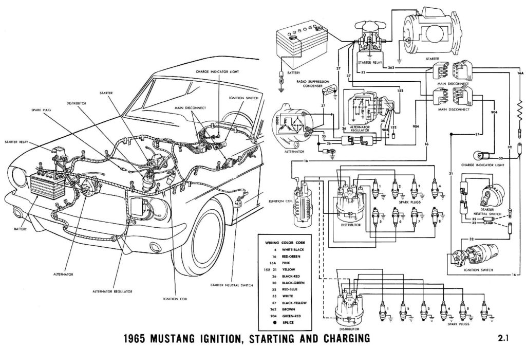
The wiring diagrams for the ignition show the various wires that are used to power various components of the vehicle. Each component is equipped with four distinct connections that are color coded. Accessories are red while the battery is yellow and the starter solenoid is green. The “IGN” terminal allows you to start the car, control the wipers, and any other functions. The diagram below shows how to connect both the ACC terminal as well as the ST terminals to various components.
The terminal known as BAT is the place where the battery is. The electrical system can’t begin without the battery. Additionally, the switch won’t begin to turn on. To locate your car’s battery, check your wiring diagram. The accessory terminals of your car are connected with the battery and ignition button. The BAT Terminal is connected to the battery.
Certain ignition switches provide an additional “accessory position” that allows users to modify their outputs independent of the ignition. Some customers may prefer to use the auxiliary output separately from the ignition. To make use of the auxiliary output, connect the connector in the same colors as ignition, and connect it to the ACC terminal on the switch. This convenience feature is great however there’s a differentiator. The majority of ignition switches are set to be in an ACC position when the vehicle is in the ACC position, but they’re in the START position when the car is in the IGN position.
Gallery of 1965 Mustang Ignition Wiring Diagram
Gallery of 1965 Mustang Ignition Wiring Diagram


