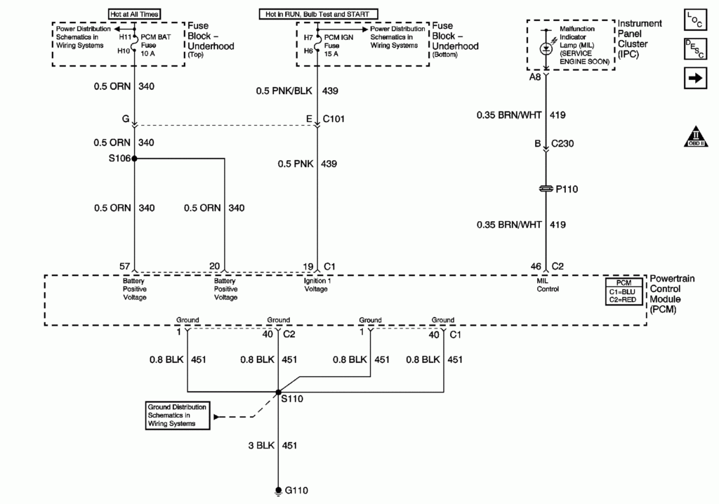
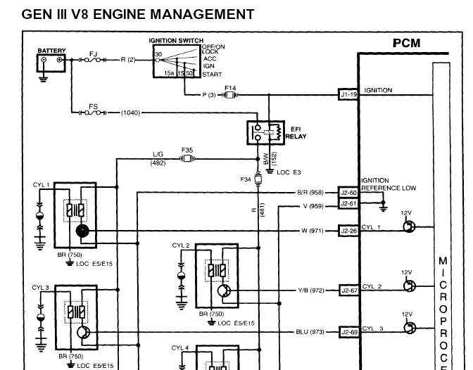
Ls1 Ignition Wiring Diagram – We will first look at the various types and functions of the terminals found in the ignition switches. They are the terminals used that are used for Coil, Ignition Switch, and Accessory. Once we have identified which terminals are used then we can recognize the various parts of the Ls1 Ignition Wiring Diagram. Then, we will discuss the roles of the Ignition switch and the Coil. Then, we’ll talk about the roles of the ignition switch and Coil.
Terminals of ignition switch
An ignition switch is made up of three different switches. These are responsible for feeding the battery’s power to various locations. The first one is utilized to power the choke by pushing it, and another switch controls the ON/OFF setting. Different manufacturers utilize their own color-coding method for different conductors which is explained in a different article. OMC uses this approach. An adapter is included on the ignition switch, allowing the installation of an tonometer.
Even though most ignition switch terminals don’t carry an original number, they may be equipped with a different number. You should first check the continuity of the wires to ensure that they are connected to the ignition switch correctly. You can do this with a simple multimeter. After you’re sure that all wires are running in good harmony and you are able to connect the new connector. The wiring loom in a factory-supplied ignition system switch is distinct.
Before you can connect the ACC outputs to your car’s auxiliary outputs it is crucial to know the fundamentals of these connections. The ACC, IGN and START terminals are the primary connection to the ignition switch. They also function as the main connections to the radio and stereo. The ignition switch turns the engine of your car ON and OFF. Older cars are identified by the alphabets “ACC”, “ST”, (for individual magneto cables) at the ignition switch terminals.
Terminals for coil
The language used to decide the model and type of an ignition coil is the most important thing. A basic ignition wiring diagram will display a range of connections and terminals, including two primary and two secondary. It is essential to identify the kind of coil you own by examining the voltage at the primary terminal, called S1. To determine if the coil is an A, C, or B coil, you should also test the resistance on S1’s.
The negative end of the chassis must be connected to the coil’s low-tension side. This is the wiring diagram you will see on the wiring diagram. The high tension part supplies positive power directly to the spark plugs. To prevent noise the body of the coil is required to be connected to the chassis. But, it’s not necessary to connect the coil electrically. The wiring diagram of the ignition will demonstrate how to connect the two terminals of the positive and negative coils. It is possible to find an issue with your ignition coil which can be identified by looking it up at an auto parts store.
The black-and-white-striped wire from the harness goes to the negative terminal. The other white wire has a black color and connects to the terminal opposite. The black wire connects to the contact breaker. You can check the connections using a paperclip to pull the wires out of the housing. Be sure that the terminals aren’t bent.
Accessory terminals
Diagrams of ignition wiring depict the wires that are used in the vehicle’s power supply. Each component is equipped with four distinct connections that are color coded. Red is used for accessories, yellow is for the battery, while green is for the solenoid for starters. The “IGN” terminal can be used to turn on the car, operate the wipers, and other features. The diagram shows how you can connect the ACC and ST terminals to the other components.
The terminal BAT connects the battery to the charger. The electrical system will not start when the battery isn’t connected. The switch also won’t be able to turn on without the battery. If you’re not sure the exact location where the battery in your car is situated, you can examine your wiring diagram to see the best way to find it. The accessory terminals in your car connect to the ignition switch, as well as the battery. The BAT terminal is connected to the battery.
Some ignition switches come with an additional position. This lets users connect their outputs to another location without the ignition. Sometimes, a customer wants to utilize an auxiliary output that is separate from the ignition. To use the auxiliary output, wire the connector in the same colors as ignition, and connect it to the ACC terminal on the switch. While this is a convenient option, there’s an important difference. Many ignition switches have the ACC position when your car is in the ACC mode and a START mode when the switch is in IGN.
Gallery of Ls1 Ignition Wiring Diagram
Gallery of Ls1 Ignition Wiring Diagram


