Honda Gx620 Ignition Wiring Diagram – Let’s start by looking at the different kinds of terminals that are found on an ignition switch. These are terminals that are used for Coil, Ignition Switch, and Accessory. Once we understand the function of each terminal, it is possible to determine the components of the ignition wiring. In addition, we will discuss the functions of the Ignition switch, as well as the Coil. Then we’ll move on to the Accessory Terminals.
The ignition switch’s terminals
An ignition switch is composed of three switches. These are responsible for feeding the battery’s power to several locations. The first switch supplies power to the choke whenever pushed, and the second is the ignition switch’s ON/OFF position. Different manufacturers have distinct color-coding systems that correspond to the conductors. OMC uses this approach. A connector can be added to the ignition switch to add the digital Tachometer.
While the majority of ignition switch terminals don’t carry an original number, they may be equipped with a different number. Verify the continuity of the wires first to ensure they are correctly plugged in the ignition switch. A simple multimeter will help you do this. When you are happy with the continuity of the wires it is time to install the new connector. If your car has an original factory-supplied ignition switch (or a wiring loom) The wiring loom may differ from that in your car.
Before you can connect the ACC outputs to your car’s auxiliary outputs it is crucial to be familiar with the fundamentals of these connections. The ACC and IGN terminals are the default connections on the ignition switch. the START and IGN terminals are the principal connections for the stereo and radio. The ignition switch’s function is to turn the car’s engines on and off. The terminals of the ignition switch on older cars are labeled with the alphabets “ACC” as well as “ST” (for each magneto wires).
Terminals for coil
Understanding the terminology that is used is the first step towards finding out the right kind of ignition coil you need. An ignition wiring diagram will display a range of terminals and connections which include two primary terminals and two secondary. Each coil comes with its own operating voltage. To determine what kind of coil you have first, you need to test the voltage at S1, which is the primary terminal. S1 must also go through resistance tests to determine if it are a Type A or B coil.
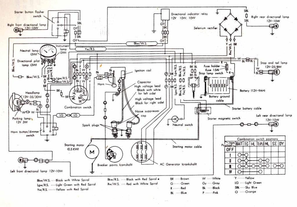
The low-tension side of the coil should be connected to the chassis the negative. This is exactly what you can see on the wiring diagram. The high-tension supply delivers positively directly to spark plugs. To reduce the noise, the coil’s body metal must be connected to the chassis. It is not required for electrical use. The diagram of the ignition wiring will also indicate how to connect the positive coil terminals. In some cases it is possible to find the ignition coil is damaged and is identified by a scan at an auto parts shop.
The black-and-white-striped wire from the harness goes to the negative terminal. The white wire also has a black trace on it, and it goes to the positive terminal. The contact breaker is connected to the black wire. You can take the black wire from the plug housing using a paper clip in case you are uncertain about the connections. Be sure the terminals do not bend.
Accessory terminals
Diagrams of ignition wiring show the different wires used to power the different components. There are generally four color-coded terminals to each component. For accessories, red stands for starter solenoid, blue for battery and blue for accessory. The “IGN” terminal can be used to start the car and operate the wipers and other operating features. The following diagram illustrates how to connect the ACC terminal and ST terminals to various components.
The terminal called BAT is the location where the battery is. Without the battery the electrical system will not get started. Additionally the switch isn’t turned on. You can refer to your wiring diagram if you’re unsure where your car’s batteries are located. The accessory terminals in your car are connected to the ignition switch, as well as the battery. The BAT connector connects to your battery.
Some ignition switches come with an additional “accessory position” that lets users modify their outputs independent of the ignition. Sometimes, customers may wish to use the auxiliary output separately from the ignition. You can utilize the additional input by connecting it to the ACC terminal. While this is a convenient option, there’s an crucial distinction. Some ignition switches are programmed to have an ACC position when the vehicle has been moved into the ACC position. They will also be in the START position once the vehicle is entered the IGN position.
Gallery of Honda Gx620 Ignition Wiring Diagram
Gallery of Honda Gx620 Ignition Wiring Diagram


