1967 Camaro Ignition Switch Wiring Diagram – Let’s first examine the different kinds and functions of terminals on the ignition switches. The terminals are the Ignition switch as well as the Coil and the Accessory. Once we understand the function of each type of terminal, we are able to determine the components of the ignition wiring. In addition, we will discuss the roles of both the Ignition Switch and the Coil. Then, we’ll talk about the function of the Ignition switch and Coil.
The terminals of the ignition switch
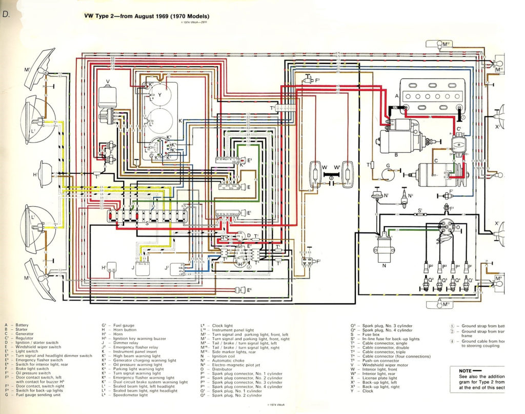
There are three different switches in the ignition switch, and they transmit the battery’s current voltage to a variety of locations. The first switch supplies power to the choke whenever it is pushed. The third is the ignition switch’s ON/OFF position. Different manufacturers employ different colors for various conductors. This is described in another article. OMC utilizes this system. An adapter is included on the ignition switch, allowing for the addition of a Tachometer.
Although the majority of ignition switch terminals are duplicated, the numbers may not match the diagram. Before plugging in the ignition switch, ensure that you check the continuity. This can be done using an inexpensive multimeter. After you have verified that the wires are in good condition, you are able to connect the connector. If you are using a factory-supplied ignition switch the wiring loom will be different from the one in your car.
In order to connect the ACC outputs to the auxiliary outputs of your car, you’ll need to understand how these two connections work. The ACC/IGN connections function as the default connections on the ignition switch. The START/IGN terminals are connected to the stereo or radio. The ignition switch is the engine’s off/on button. On older vehicles the ignition switch’s terminals are identified with the alphabets “ACC”, and “ST” (for distinct magnetic wires).
Terminals for coil
Understanding the terminology utilized is the first step to finding out the right kind of ignition coil you need. A simple diagram of the wiring will show a variety of terminals and connections comprising two primary and two secondaries. Each coil comes with its own operating voltage. To determine what kind of coil you own, the first step is to test the voltage at S1, the primary terminal. It is also recommended to test S1 for resistance to determine whether it is an A, B, or C coil.
The chassis’ negative must be connected to the low-tension side. This is what is known as the ground for the ignition wiring. The high-tension supply supplies the spark plugs with positive electricity directly. It is necessary for suppression purposes that the metallic body of the coil is connected to its chassis, but not essential. The wiring diagram for ignition will also indicate how to connect the positive coil terminals. In some cases, you’ll find that the ignition coil is damaged and can be diagnosed with a scan at an auto parts shop.
The black-and-white-striped wire from the harness goes to the negative terminal. Positive terminal receives the second white wire, which is black in its trace. The black wire connects to the contactbreaker. You can remove the black wire from the housing of the plug by using a paperclip If you’re unsure of the connections. It is also important to ensure that the terminals are not bent.
Accessory terminals
The wiring diagrams for the ignition show the different wires that power the various components of the vehicle. There are generally four colors-coded terminus of each part. The accessories are red, the battery is yellow, the starter solenoid green. The “IGN” terminal is used to start the vehicle, controlling the wipers and various other functions. The diagram shows the connections between the ACCas well as ST terminals.
The battery is attached to the terminal whose name is BAT. The battery is necessary to allow the electrical system to begin. Additionally, the switch won’t start. The wiring diagram will inform you the location of your car’s battery. The accessory terminals of your car are connected to the ignition switch, as well as the battery. The BAT connector is connected to your battery.
Certain ignition switches have an additional position. It allows users to access their outputs from another location without having to turn on the ignition. Users may wish to utilize the auxiliary output in addition to the ignition. Use the auxiliary output by connecting it to the ACC terminal on the switch using the same colors. While this is a convenient feature, there is one significant difference. Most ignition switches are configured to show an ACC status when the car’s in either the ACC or START positions.
Gallery of 1967 Camaro Ignition Switch Wiring Diagram
Gallery of 1967 Camaro Ignition Switch Wiring Diagram


